Moulding Flexible Links


In this tutorial we will be designing a mould for a flexible link and making one with Sugru. With the link, you can join two other 3D printed pieces together.

This technique can be used to build flexible areas in a robot, allowing it to have more movements than being directly driven by a servo.


Why does this matter? For some tasks, robots need to be flexible but still have a form. Combining the flexible links with structural aspects (e.g., vertebrae) helps to achieve this.

Going further, you can use these skills to make more complex moulds for flexible pieces. In the future when multi-material 3D printers are widely available, creating interesting hybrid pieces will be common.

Supplies Needed
  • Autodesk Inventor
  • Mouse with right/left click (middle is handy for panning the view)
  • 3D Printer, Filament
  • Sugru or Oogoo
  • Dish soap
  • Xacto knife
  • Small scissors
Here are the completed moulds to download, in Inventor and .stl format:

Download Example Moulds

Design of the Hub


The first part that we need to tackle in creating our flexible link is the hub. The hub will give the Sugru something to adhere to, and 'combine' with itself.

Before we dive into all the design screenshots, here is what the inside of the flexible link looks like, without the hub, as the cylinders did not connect properly (lack of material).


OK, now let's start on the design! Fire up Inventor and create a new part...

1. Start off by creating a new sketch. This is half of what the hub looks like, as it will be revolved around its middle axis. The circle will be one of the holes going through the entire object.

2. Finish the sketch, and now revolve it. The revolution should be the full 360 degrees, and it will be about the middle axis.

3. Share the original sketch, and now extrude the circle all the way through.

4. Now we need to work on adding the circles for the other sides. We can start this by creating a new work plane, offset from the origin plane (in this case, YZ).

5. From the new work plane, create a new sketch. Add a circle to it, with the same dimensions as in the original sketch.

6. Create another new work plane, this time as an offset from the bottom (in our case, the XY plane).

7. Create a new sketch based off of the plane, and add a circle.

8. Extrude the circles all the way through the hub. This is what the final result will look like.


The reason why there is a larger cylinder at the bottom of the hub is to serve as a stopper when it is in the mould. This ensures that the hub is always at the same distance outside of the mould.

It's important that the hub is very smooth, otherwise it could lead to tearing a portion of the material. Be sure to remove the frays from the hub after printing, as the supports will add some edges to it.

Now that the hub is done, let's go on to the best part: the mould!

Design of the Mould


Now it's time to make the mould. The key thing to understand about moulds is that it is a 'negative' of whatever shape you are creating. For example, we will be creating a shape, then setting it to be cut out from a rectangular block.

Another example to illustrate this concept in your mind, is if we dig a hole in sand, and then fill it up with some sort of material. If the hole is narrow and deep, the resulting object from the material will also be narrow and long.

So, that is what we will be doing- creating a shape, and then subtracting it. It's important, just like with the hubs, that the shape will be smooth. Any sharp edges will make the material want to break. Also, there has to be enough room for the hub to sit in it.

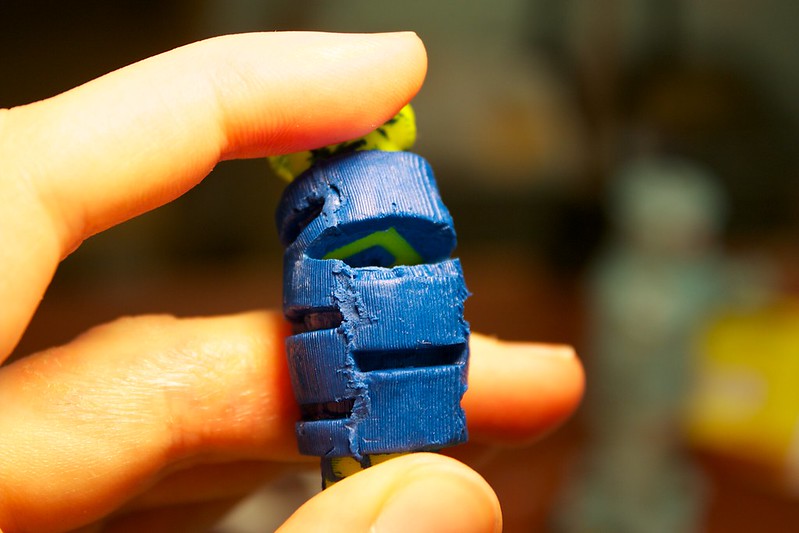
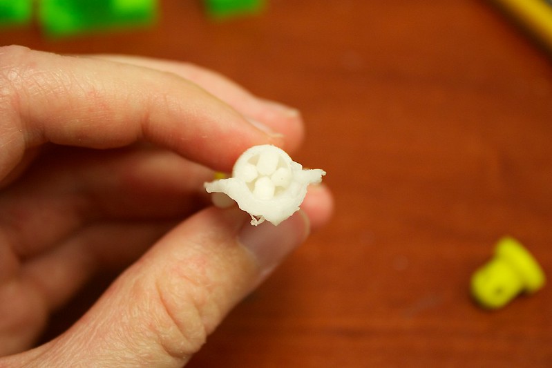
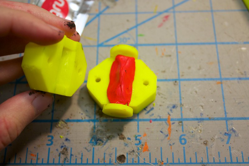
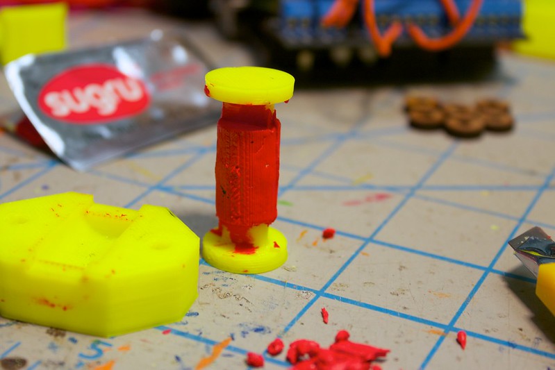
Here is an example of what can happen if there are sharp edges in your mould:


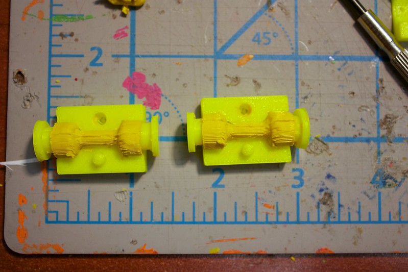
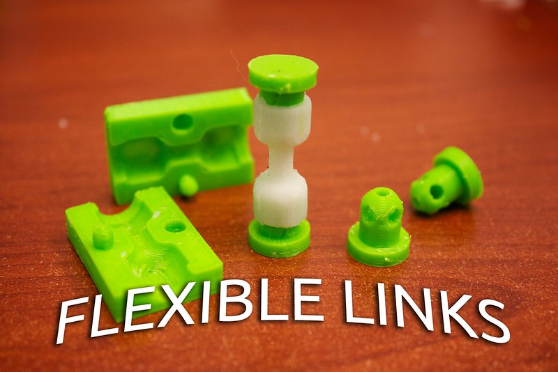
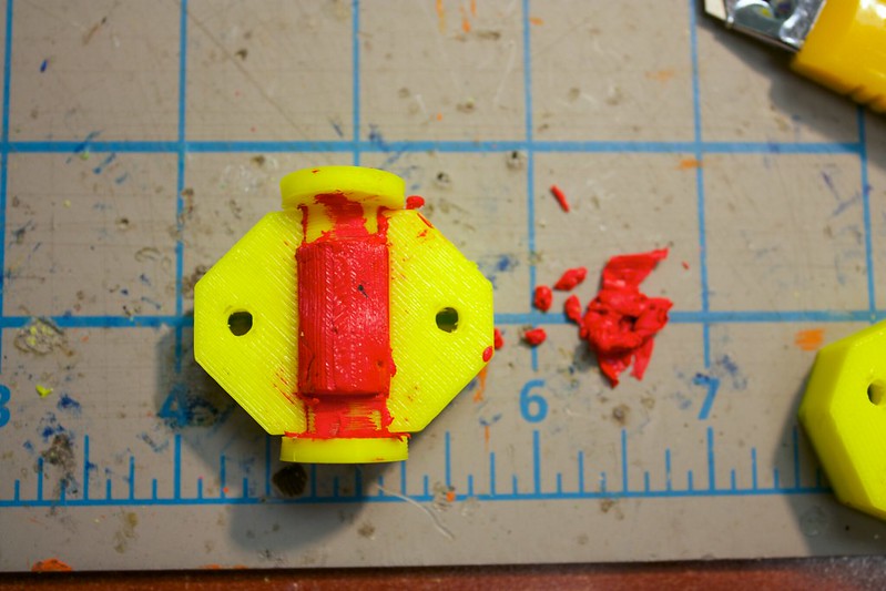
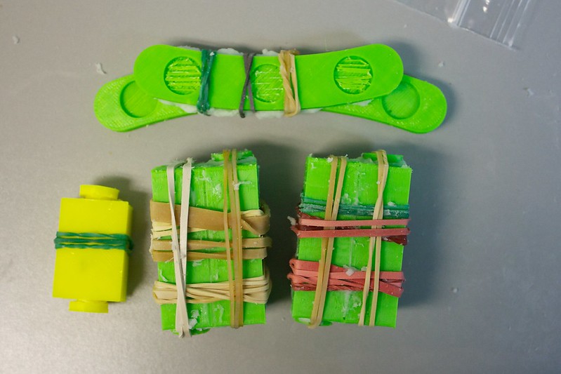
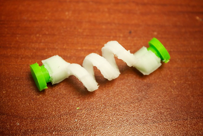
Here is an example of what we WILL be making, with nice an smooth edges:


OK, enough talk- Let's jump into the design!

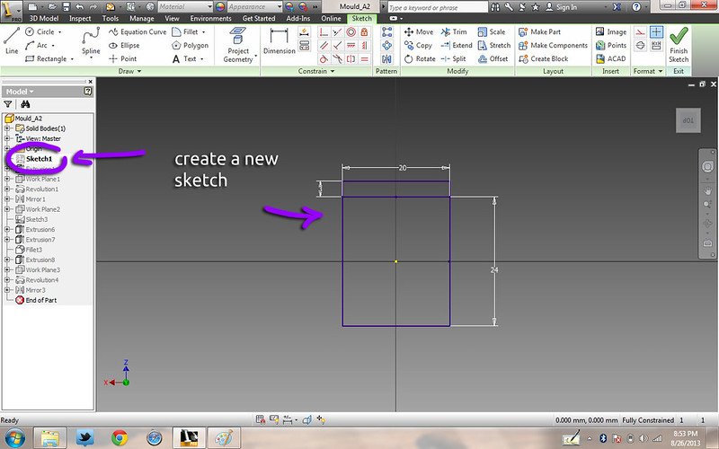
1. Create a new sketch- for the outline of the mould.

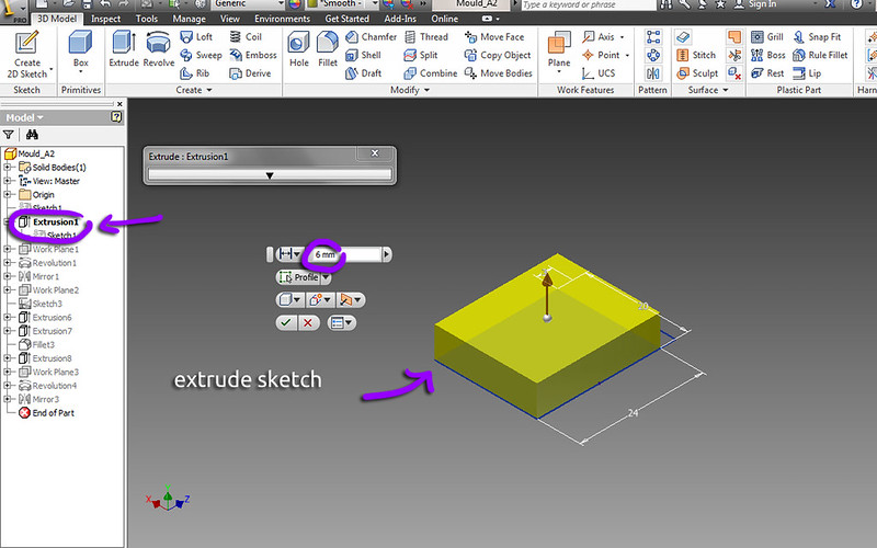
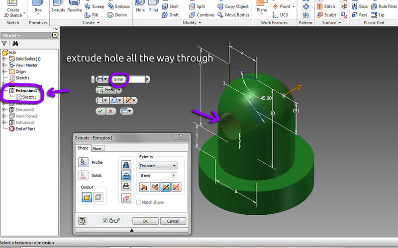
2. Extrude the sketch.

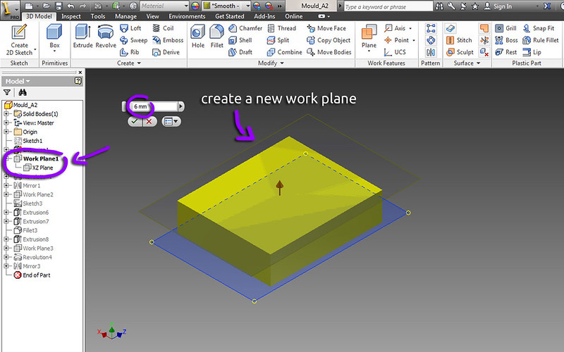
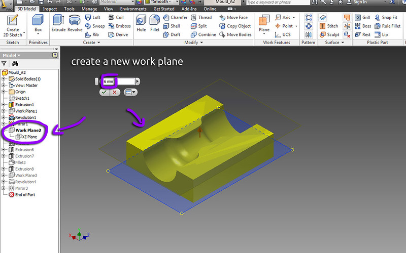
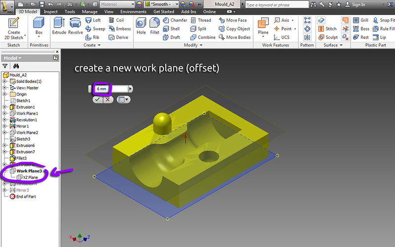
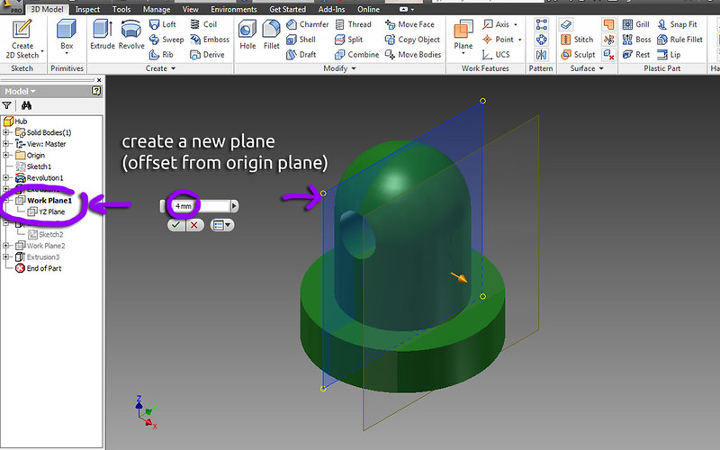
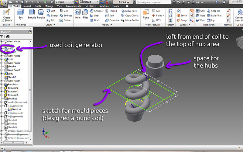
3. Create a new work plane- the same offset distance as the length of the previous extrude.

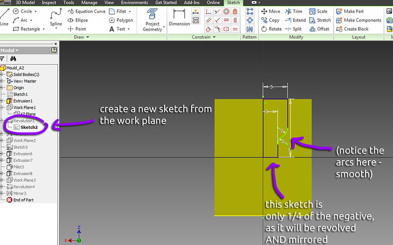
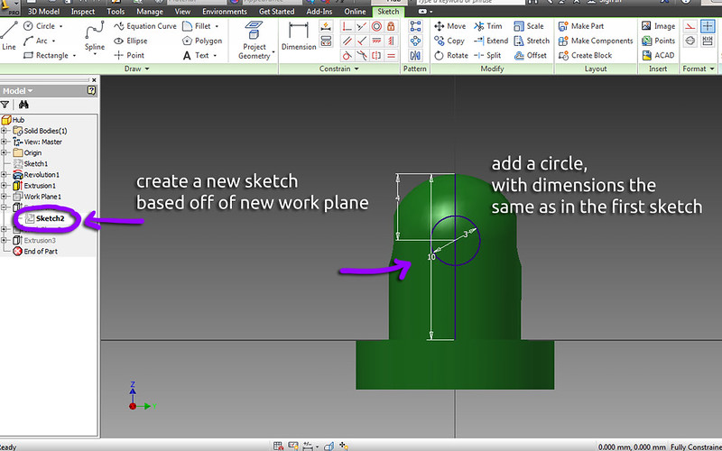
4. Create a new sketch on the work plane. This will be our negative for the mould. It only has to be in one quadrant, as the sketch will be revolved and then mirrored. Note the arcs used to smoothly move from the size of the hub to the size of the flexible middle area.

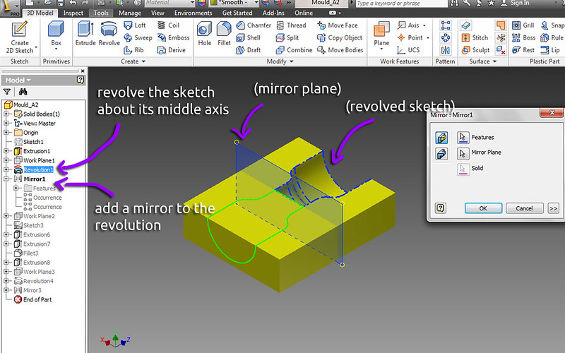
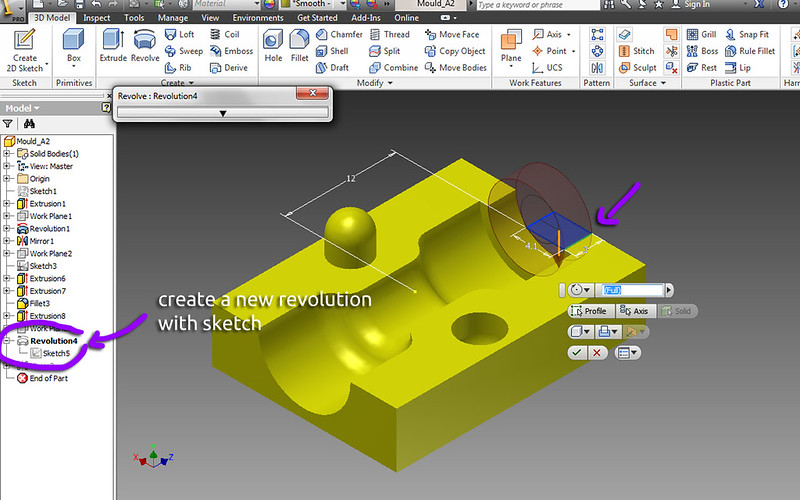
5. Revolve the sketch, and mirror the revolution. Be sure the revolution is set to 'cut', so that it can remove the area from the prior extruded block.

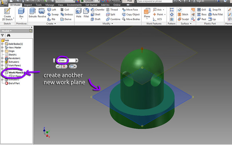
6. Again, create a new work plane that is the same offset as the length of the extruded block.

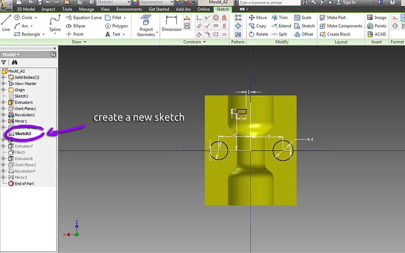
7. Create a new sketch and add two circles. These two circles are 'stubs', for positioning the mould halves together properly.

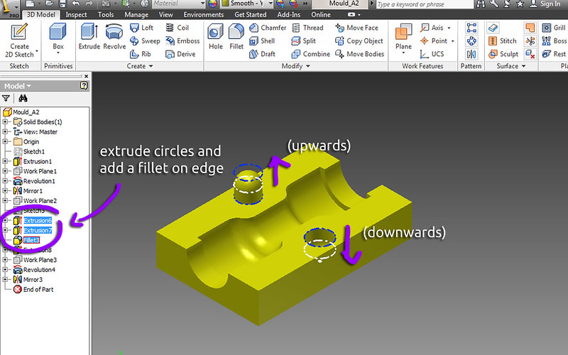
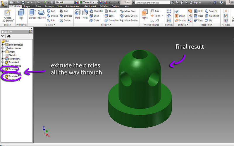
8. Extrude the cirlces upwards and downwards, and be sure to add a fillet to the edge of the cylinder.

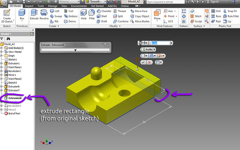
9. Extrude the additional rectanlge piece from the original sketch (share the sketch if you haven't already)

10. Again, create a new work plane.

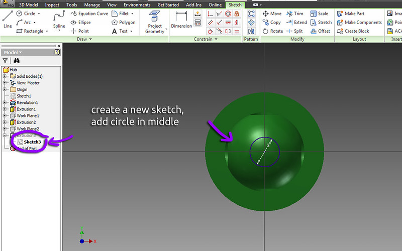
11. Make a new sketch based off of this work plane. Add a rectangle- this will be the area for our hub to sit in.

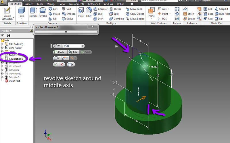
12. Revolve the sketch about its middle axis.

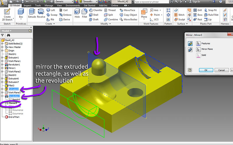
13. Mirror the extruded rectangle AND the revolution.

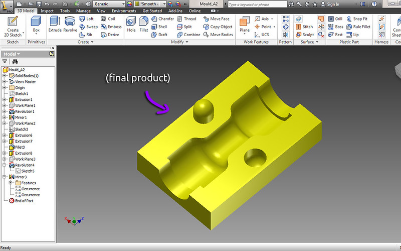
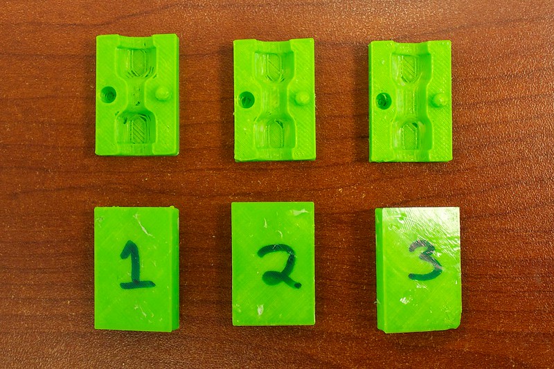
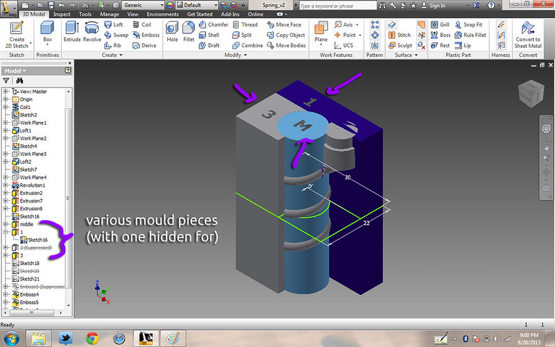
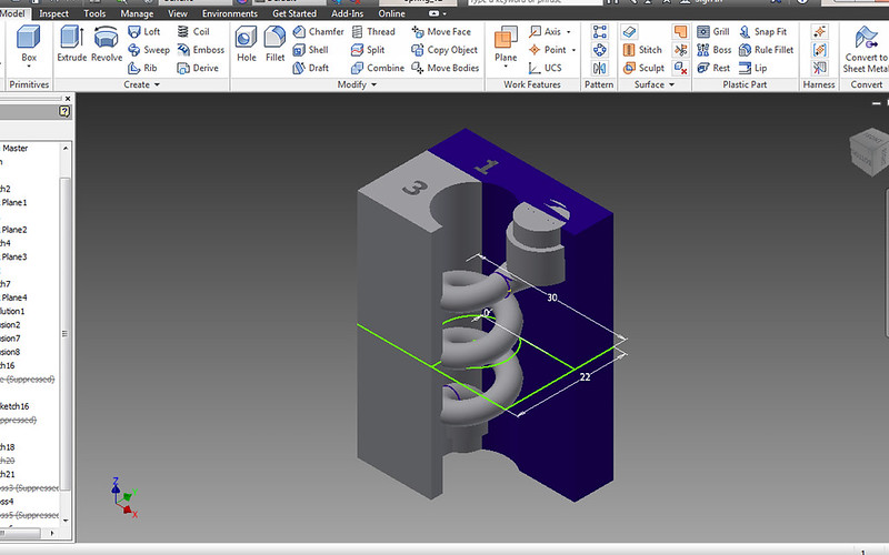
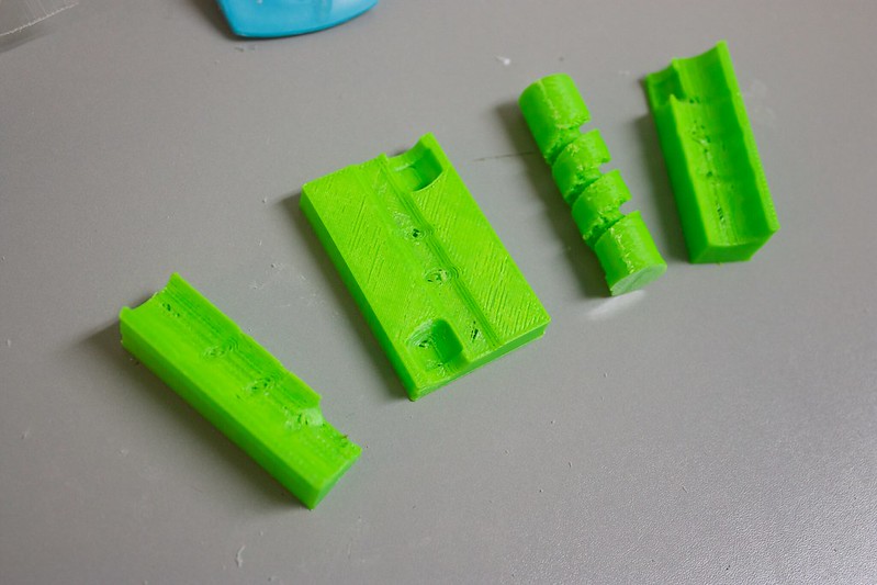
14. Here is what the final result should look like.


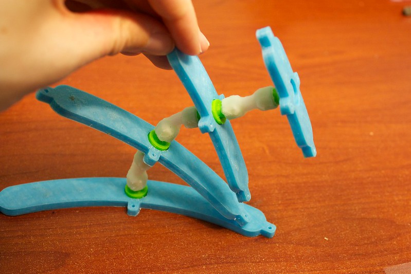
As you might have noticed while designing the piece, there are dimensions that you can modify to create a different shape. It's fun to try different things out, like a thicker link, or a longer link. (We'll talk about this more in the Using the Flexible Links section).

Advanced Idea: Spring!


What other shapes can be created? Can you make a SPRING? We were wondering exactly the same thing... so we tried it out!

It's not very sturdy, but it retains its shape and is springy when pulled apart:


Here is the general gist of how we made it:

Here you can see the mould pieces surrounding a spring. There are 4 pieces in all (one was hidden for visibility sake).

With the middle mould hidden, you can see the spring more clearly. Each side of the mould has little indents for where the spring intersects it.

Here's a 'close up' of the spring. It was created using the coil generator. You can see the sketch for the mould pieces, this was designed specifically around the coil. The ends of the coil are joined to the hubs using lofts.

When printed, this is what the pieces look like. It's cool to see how the middle looks similar to a drill bit in a way.


There's much more fun to be had experimenting with this... just make something and try it! See if it works!

Summary


By now, at the end of this tutorial, we hope that you are inspired to try making a flexible link. It's a fun process that can be modified to make more interesting things.

If you did make a flexible link- congrats! Attach it to things and see what happens when pulling the fishing line. They are just fun to goof around with. Make it into a real robot, and add some servos to the fishing line as well ;)!

If you have any questions, feel free to ask on the forum.


"I just learned how to make a FLEXIBLE LINK! Interesting! #RoboBrrd"


Many thanks to Sugru for the free sample pack and feedback. Also, while testing different techniques and designs, feedback from the community was incredibly useful as well- so thanks!
RoboBrrd Learn I just learned how to make a FLEXIBLE LINK! Interesting! #RoboBrrd