Here are the steps to get the RoboBrrd Brain Board ready to be working with the other areas of the robot, like the servos, RGB LED eyes, and photocells. If you want to customize your RoboBrrd to work with certain pins, this is a good place to do it. You can even completely skip these steps all together if you want to go your own way with wiring up the robot.
The wire that we're using in the below steps is 21 AWG single core. We use electrical tape instead of heat shrink tubing, but if you have some of that you can also use it!
Extra - Step 1
Servo Headers
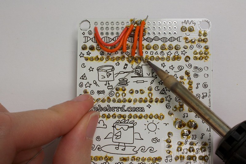
This is for being able to plug in the servos to the RoboBrrd Brain Board directly. This can be done using three 3x1 M header pieces and some extra wire. Align the headers in front of the screw terminal pin that you will be using. After soldering the headers in, you can create a jumper from servo power to the middle rail, and ground to the bottom rail. The signal pads will need a jumper to go to their corresponding pin. Check out the photos below for an illustration of this.
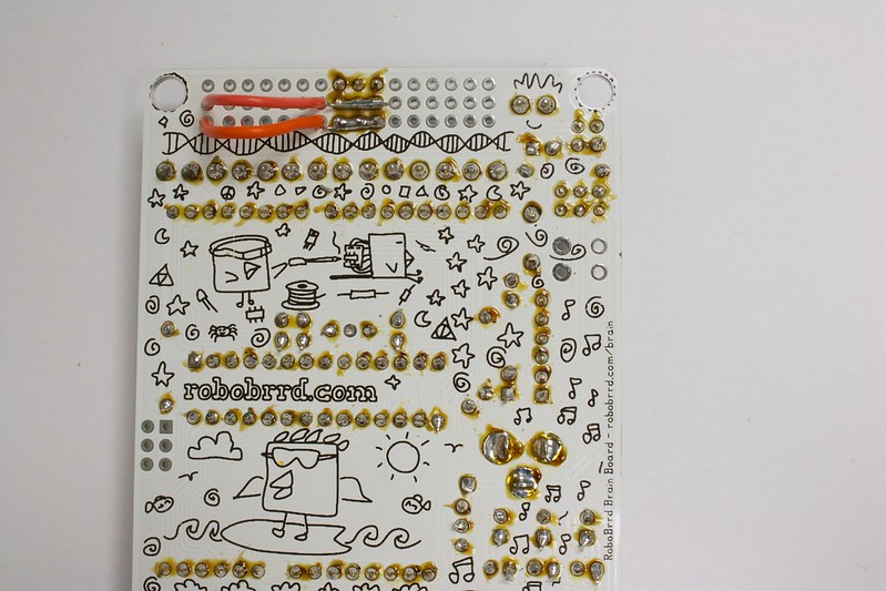
Later on when you plug in your servos, if you wired it like in these photos, then the brown wire will go towards the inside of the board, and the orange/yellow wire towards the outside edge of the board. This is because the brown wire is for ground, red for power, and orange/yellow for signal. It matches up with the wiring we did on the back of the board.
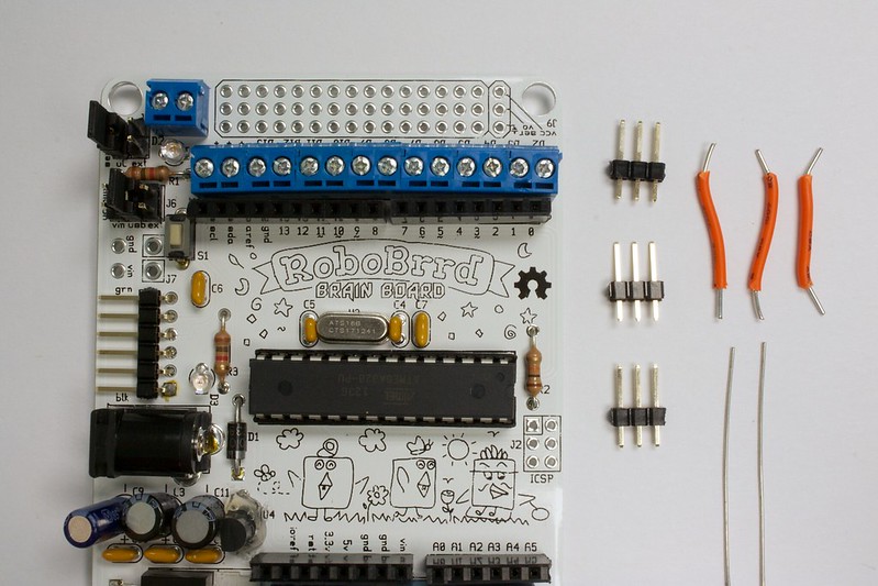
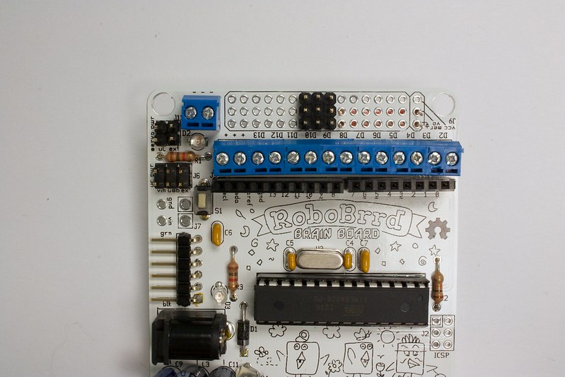
1. Start out with three 1x3M header pieces, and some extra wire
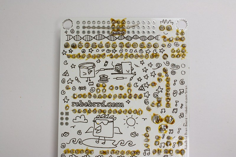
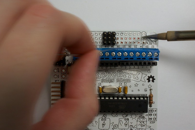
2. Place the headers on the board, and flip it over. Solder it in!
3. This is what it will look like when they are soldered in
4. Add on some wire (without insulation), to create a bridge between pads in the same row. A good piece of wire could be one of the capacitor legs that we trimmed, back in the soldering section!
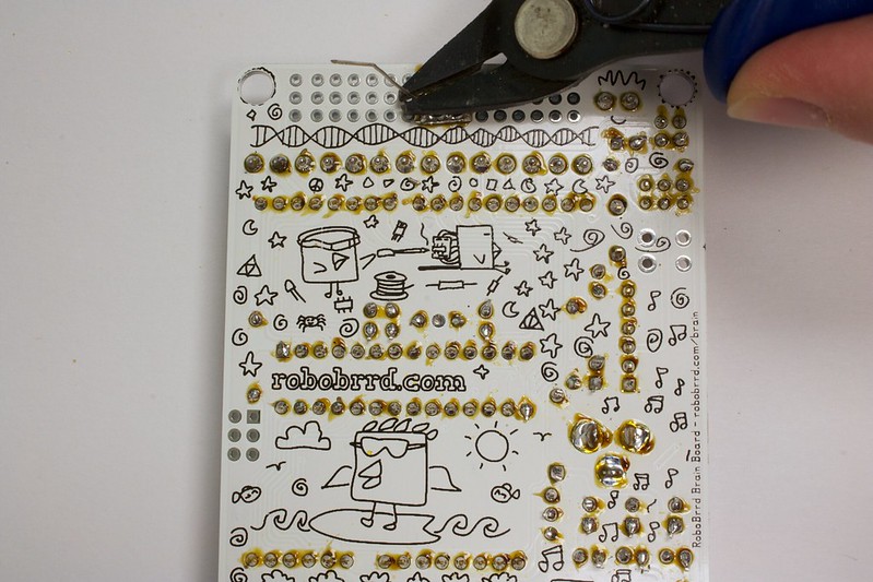
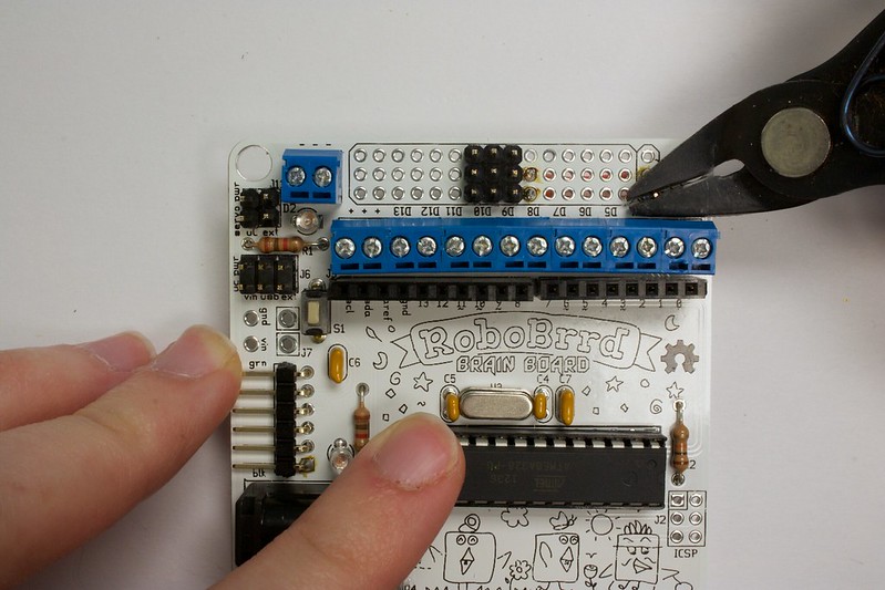
5. When it is stuck on, trim off the excess
6. This is what it looks like with the bottom one done
7. Do the same for the middle row
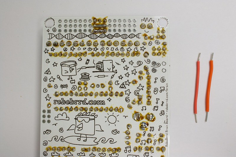
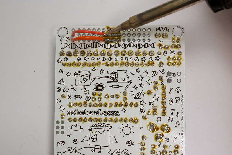
8. Now, grab another two pieces of wire. These will be used to jump between servo voltage and the middle row, and ground and the bottom row.
9. Place the wires through like this
10. Flip the board over, be careful to not lose the wires!
11. Solder it in like this
12. Trim off the parts of the wire that stick out
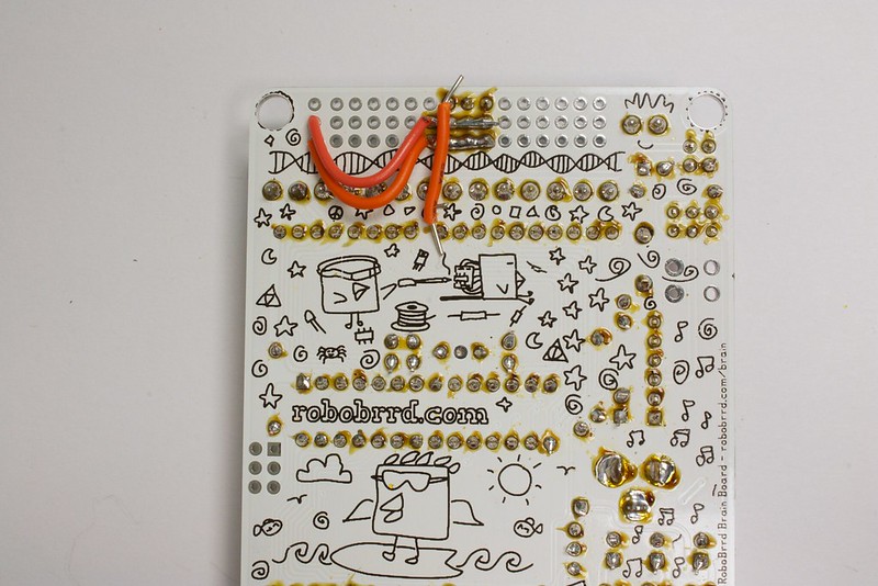
13. Flip the board over, and add some solder to connect the jumper and the row together
14. It should look like this afterwards!
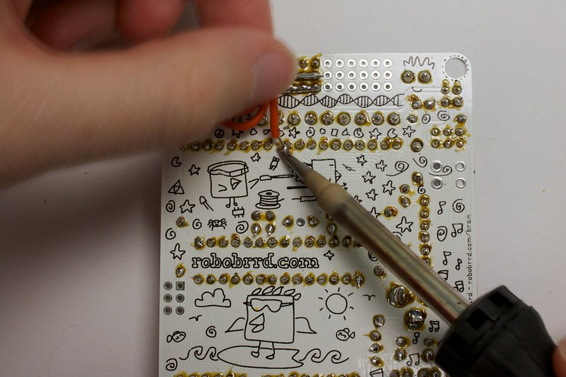
15. Now, with the three pieces of wire we had in the beginning, grab one of them and place it so it connects between the pins
16. Solder it to the pads
17. Hooray, it's connected!
18. Do the same for the other two
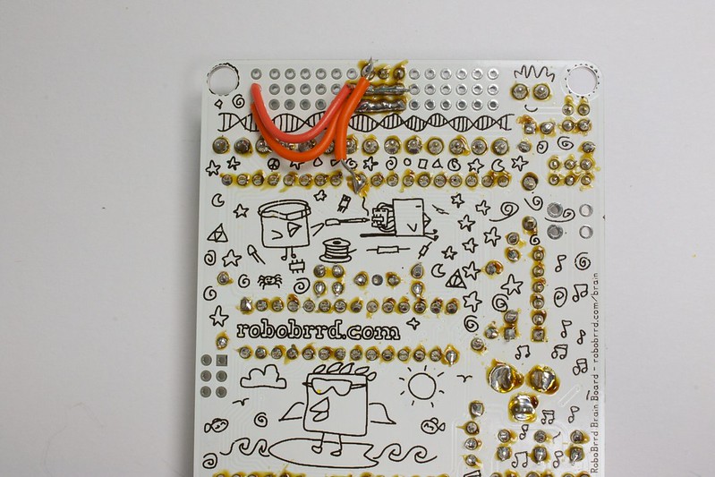
19. This is what it should look like when done, be careful that none of the jumpers are accidentally touching eachother
20. Flip the board over, this is what it will look like when it's done!
Extra - Step 2
RGB LEDs
.
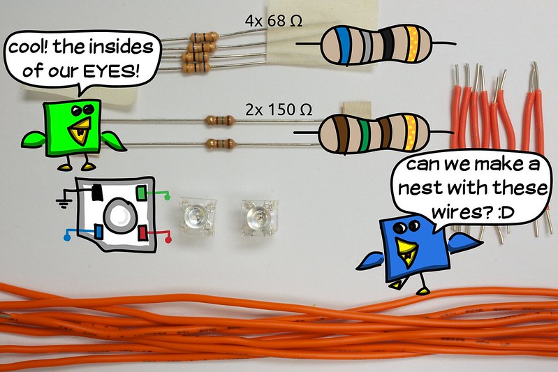
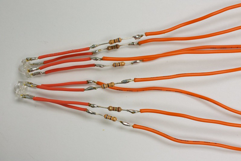
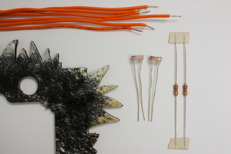
Behind the googely eyes of a RoboBrrd are a pair of RGB (red green blue) LEDs! For this, we will need 8 strands of long wire. The wire has to be able to reach from the eye sockets to the bottom of RoboBrrd for it to be plugged in. We also need 8 strands of shorter wire, for connecting directly to the LED. Next up, 2x 150 ohm resistors, and 4x 68 ohm resistors. Of course, we also need the two piranha RGB LEDs!
We will be soldering the shorter pieces of wire directly to the LED first, then adding the resistors and additional wire. For the resistors, the 150 ohm goes on the red lead, and 68 ohm goes on the green and blue leads. With the LED facing towards you (with the bump facing you): Starting at the diagonal edge of the LED first and moving clockwise, the order is: BLUE, GND, GREEN, RED. Check out the photos below for more explanation!
The pics below go through wiring up one of the LEDs. If your RoboBrrd has two eyes (I hope it has two eyes, otherwise it's a CyclopsRoboBrrd), you'll want to do the same steps below for the other LED.
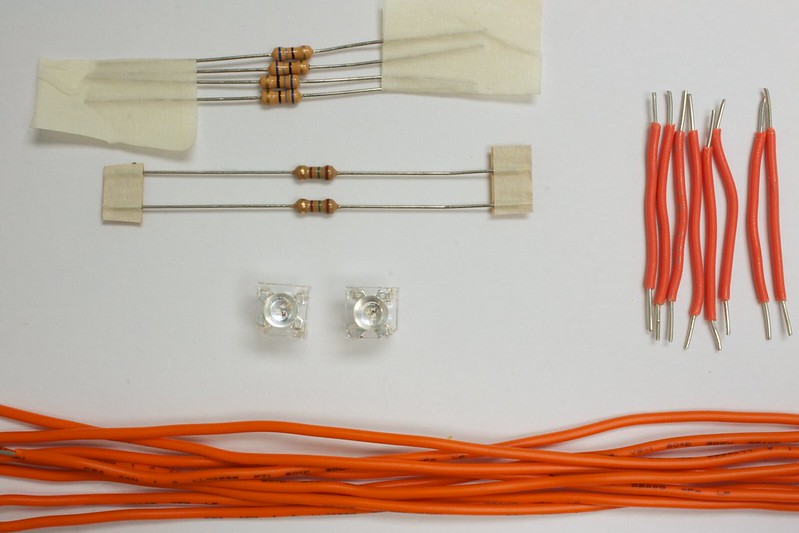
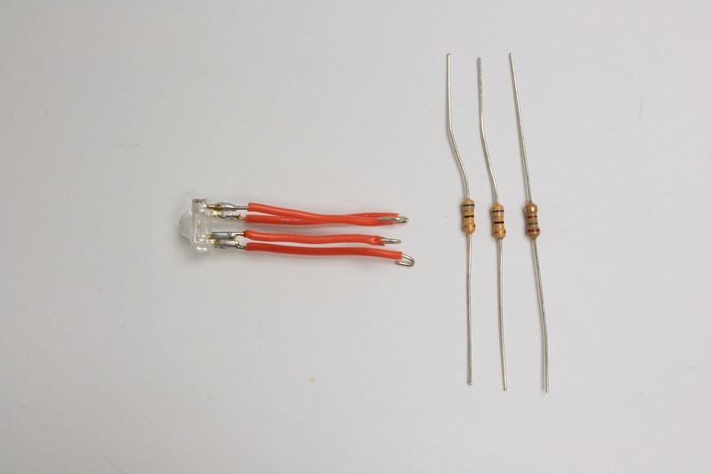
1. Here are all the stuff that you will need, long wires, short wires, 2x 150 ohm, 4x 68 ohm, and the two RGB piranha LEDs
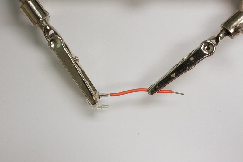
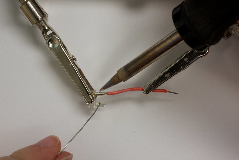
2. Here I'm using a 3rd hand tool to help solder the wires on, I prefer to not use a hook and loop because the leads on the LED aren't very long. So instead, just soldering it straight on
3. Solder it!
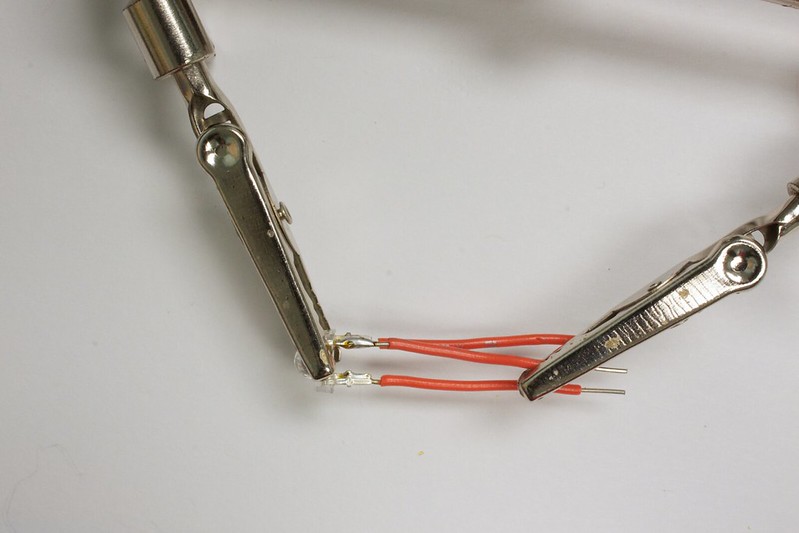
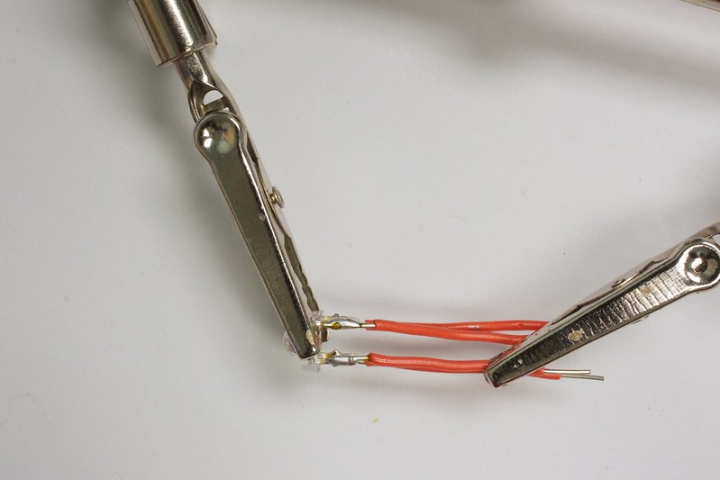
4. Add on more of the wires
5. Solder them!
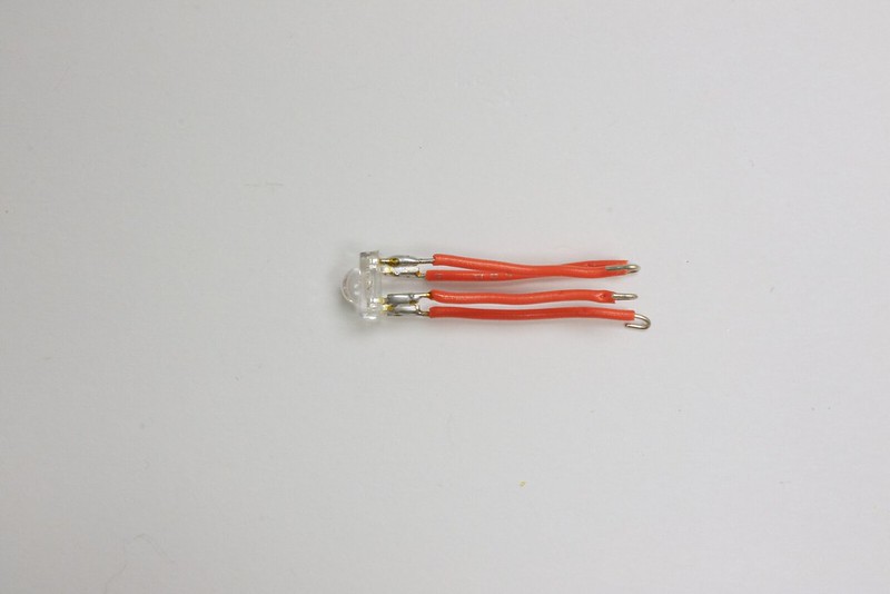
6. Now, with the ends of the wire, twist them inwards a little
7. So that all four of them will look like this
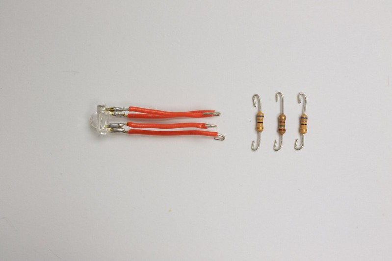
8. Now grab two of the 68 ohm resistors, and one 150 ohm resistor
9. Cut the resistors so their leads are shorter
10. Curl in the ends of the resistor leads
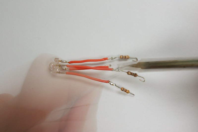
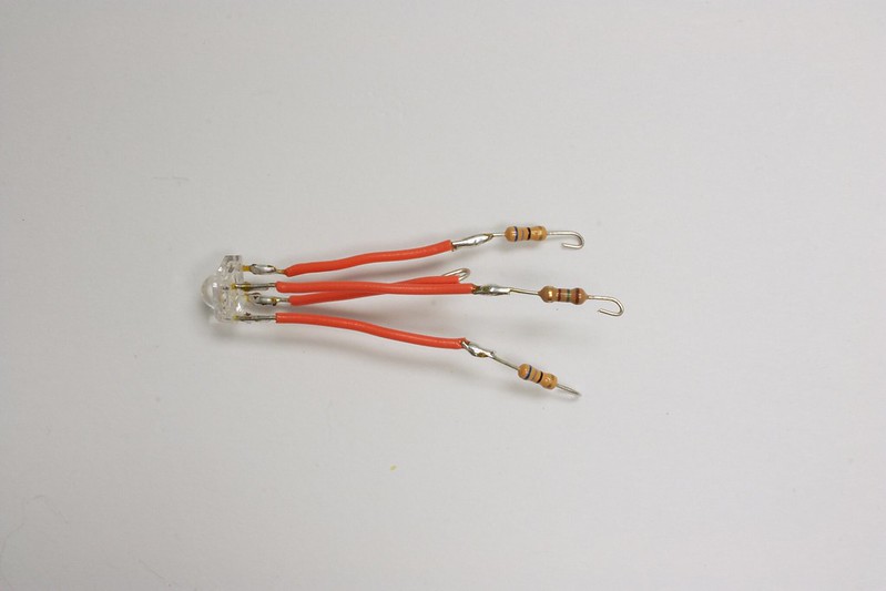
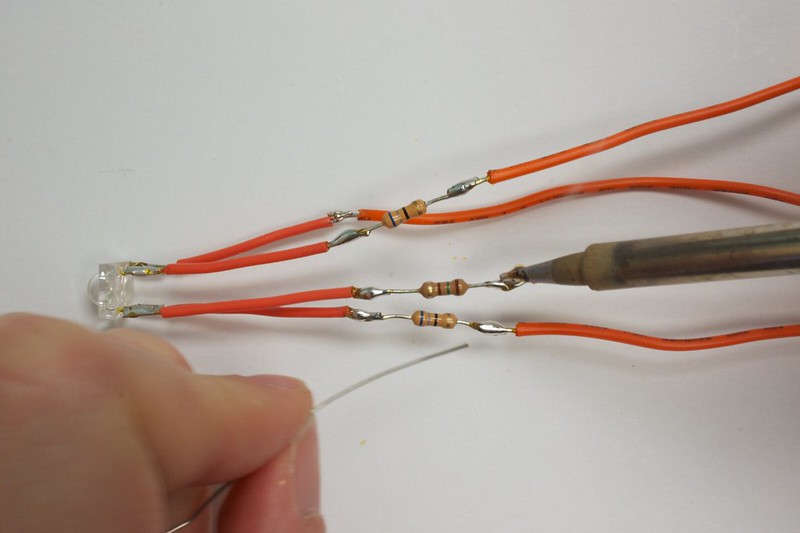
11. Attach them to the wires on the LED --> REMEMBER to place them on the right lead (see pic and explanation above!)
12. Now solder them together
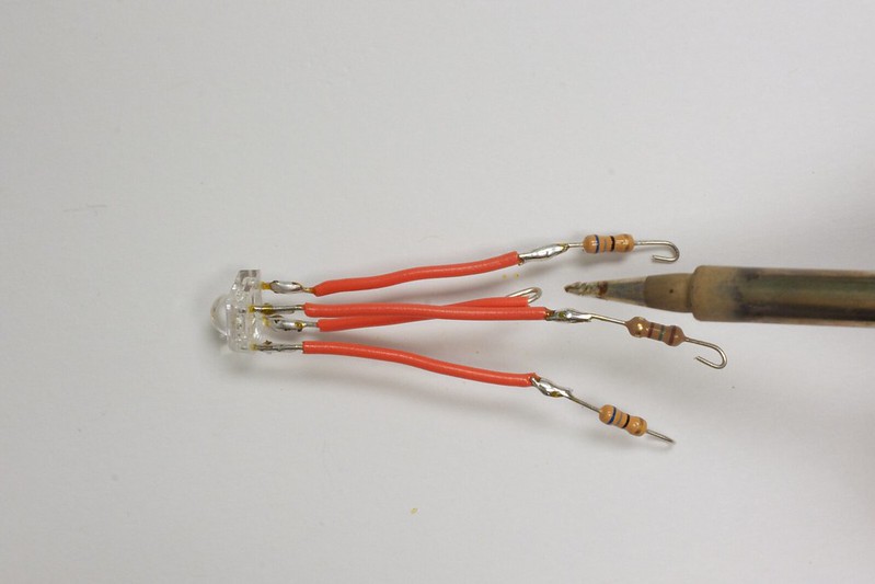
13. Solder! w00t
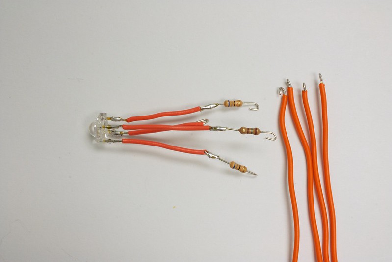
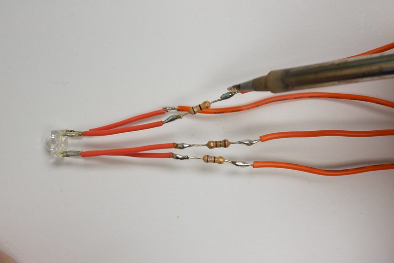
14. This is what it looks like when done
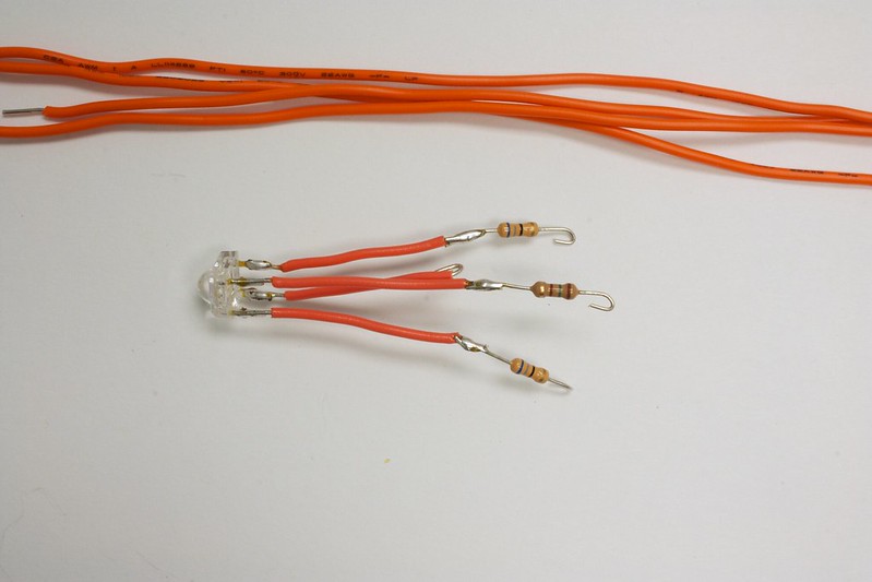
15. Now grab four of the long wires
16. Curl the ends inwards
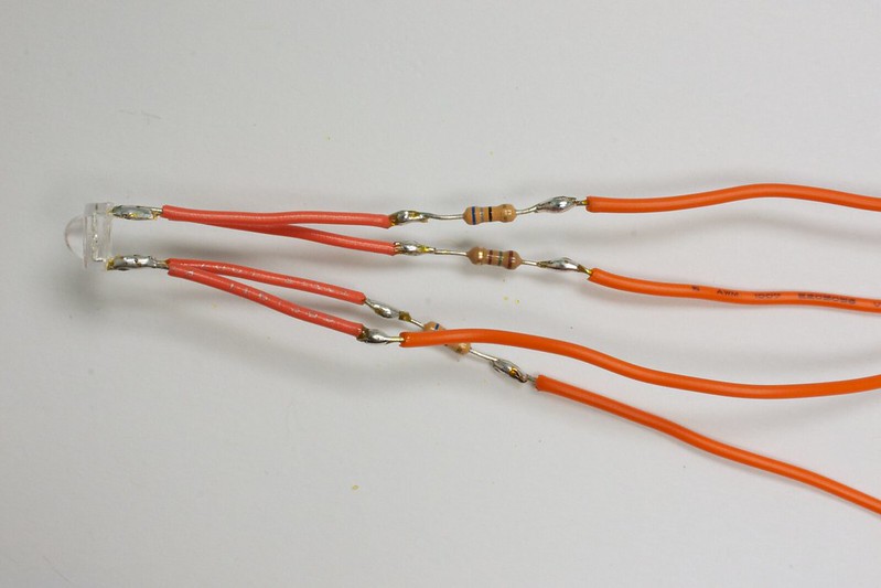
17. Attach them to the ends of the resistors (and the one short wire)
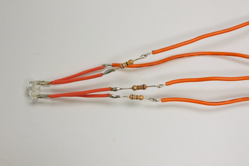
18. Solder it together
19. Solder!
20. The soldered connections should be strong when finished. Check it by tugging lightly on them to make sure they don't come apart
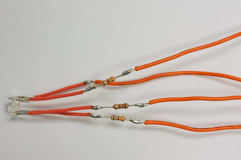
21. Do the same for the other wiring as well
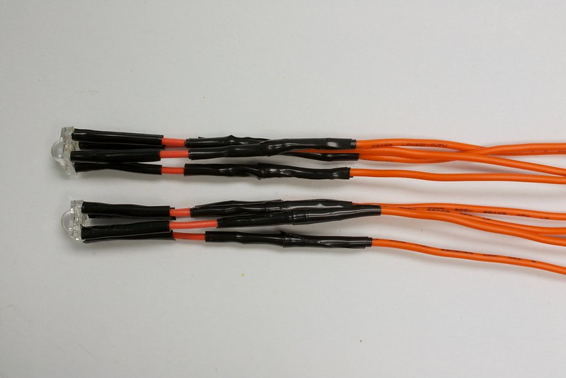
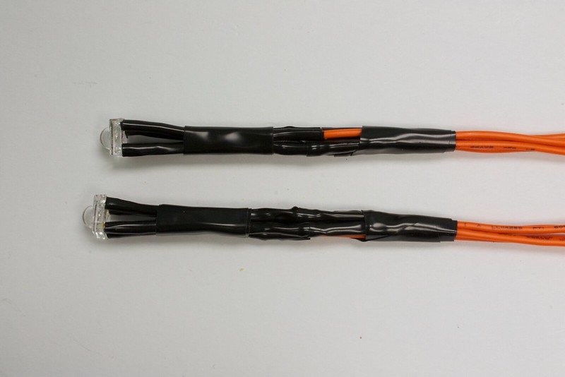
22. This is what the two of them should look like when completed
23. If you have heat shrink tubing, add that to the exposed wires. Otherwise, you can wrap pieces of electrical tape around!
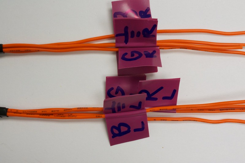
24. Labeling each wire is a good idea and will speed things up in the end
25. Add on some more tape to keep the wires together, and this is what it should look like when done!
Extra - Step 3
Photocells
RoboBrrd needs a sense of light! The photocells are light dependent resistors (LDRs), so their resistance changes depending on how much light there is. We can use a simple voltage divider to get the sensor values into an analog input in the Arduino.
The best way to wire this up is by putting the LDR through the space in RoboBrrd's front face first, then attach the wires. We will need 6 long wires, two 1k ohm resistors, and of course the two photocells. See the below photos for more details on what to solder and such!
1. Here is what we will need: the front face of your RoboBrrd, 6 long wires, 2x 1k ohm resistors, and the photocells
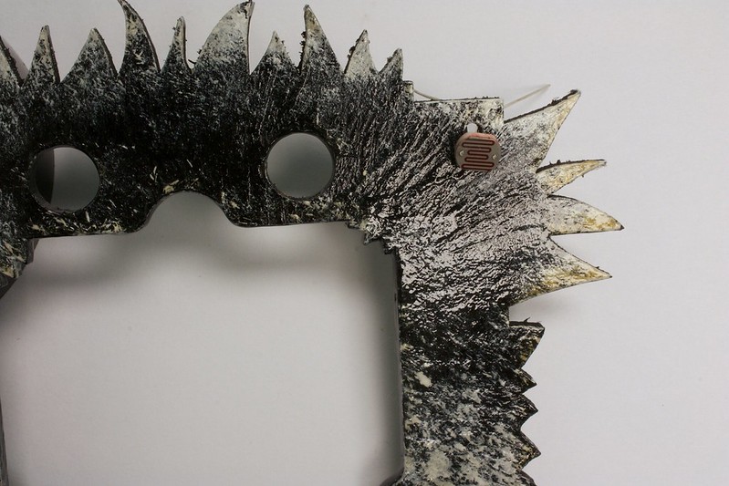
2. Poke the photocell through the hole in the corner of the front face
3. The leads should go through like this
4. Gently position them so they protrude a little bit from the front face, also spread their leads apart and make sure they are not touching
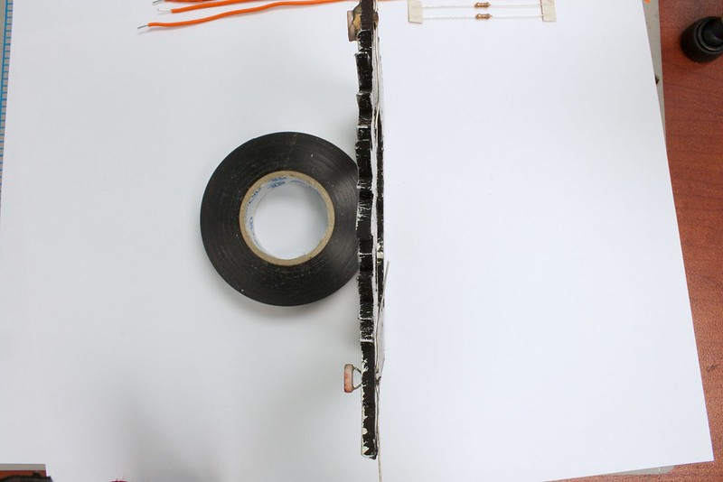
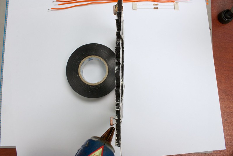
5. Add glue around the exposed leads
6. Flip the front face over, there should be glue like as seen
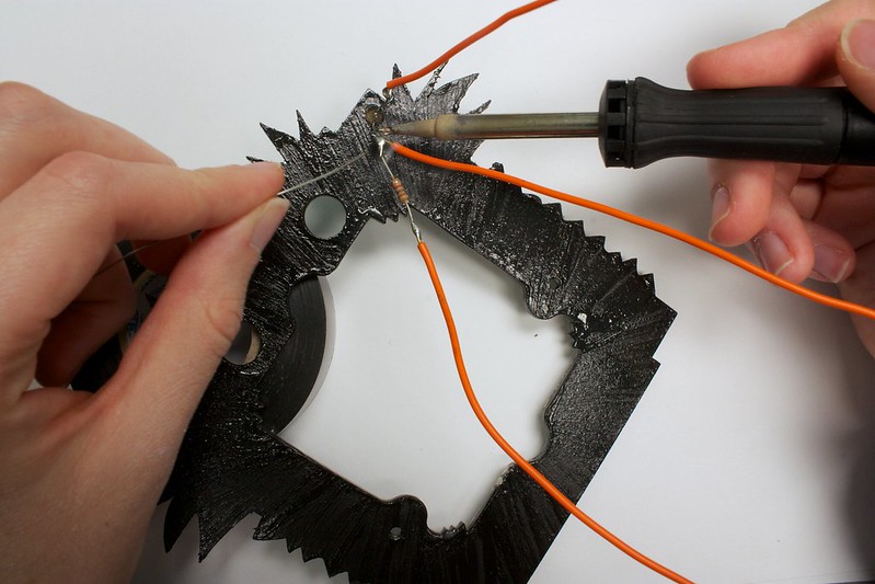
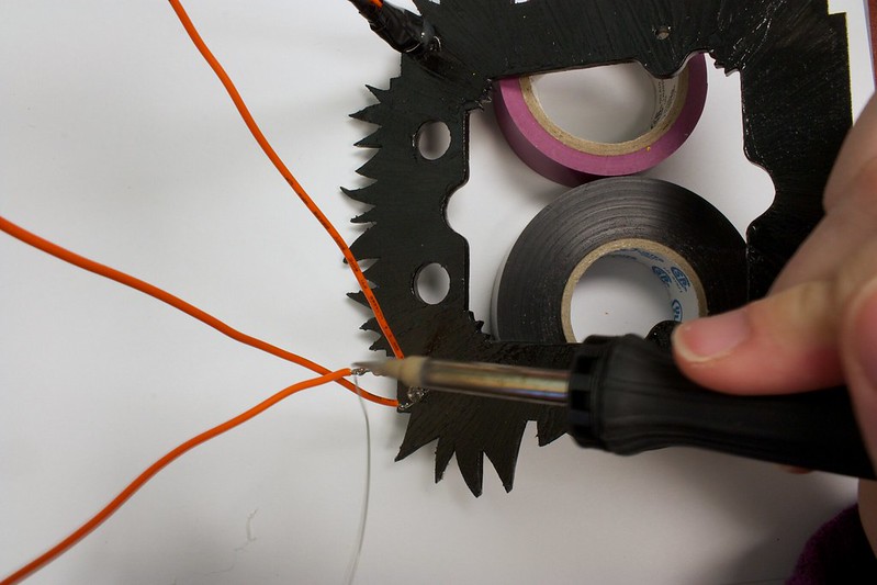
7. Cut the leads from the photocell so they are shorter. Add on a long wire to one side, and a resistor (with its long wire) to the other side. Hook another wire onto the photocell lead before the resistor.
8. Solder the connections
9. Solder!
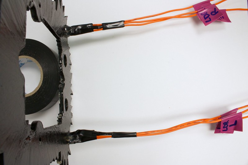
10. Add heat shrink tube or electrical tape to the exposed leads
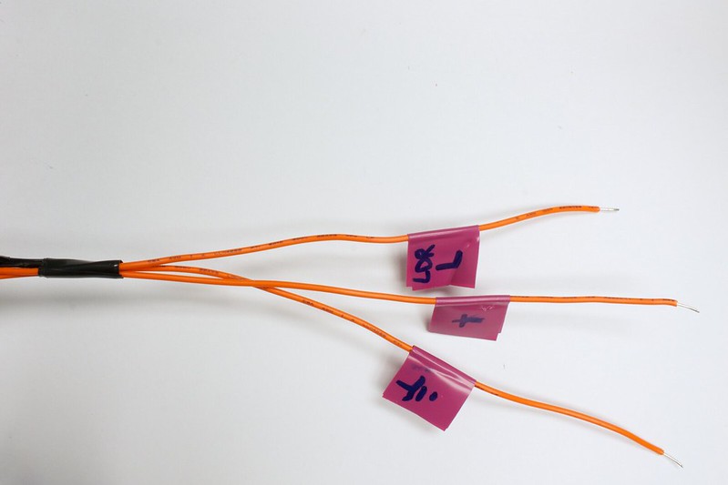
11. Remember to label which wire is which! The wire after the resistor is GND, before the resistor is the analog in (labeled here as 'LDR'), and the wire on the other side is + (where the 5V will go)
12. Do the same for the other side as well
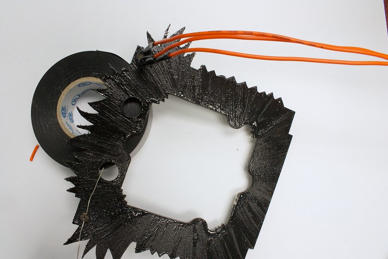
13. Time to add tape to the other side
14. This is what it will look like when both sides are done!
Extra - Step 4
Gluing
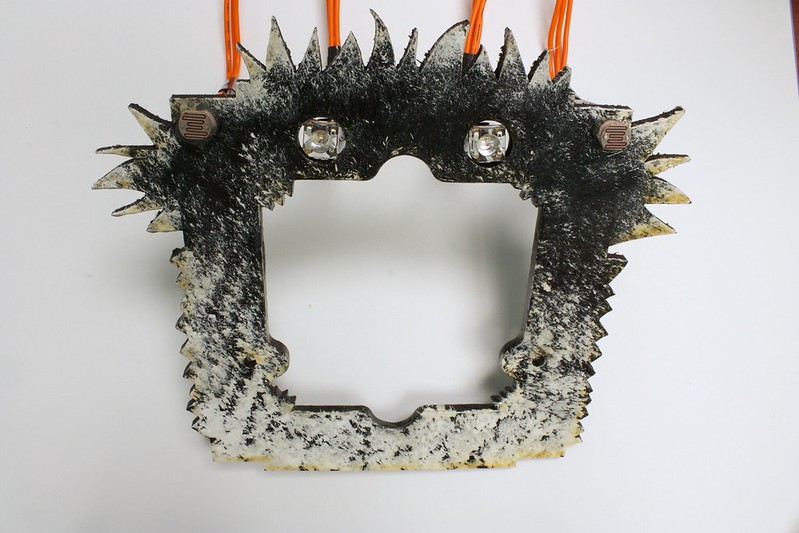
We need to add the RGB LEDs to RoboBrrd's eyes. At the same time, make sure that everything on the front face of RoboBrrd is secured. Adding hot glue around the LDRs and RGB LEDs is a good idea.
1. This is the front face with the RGB LEDs inside of the eyes, from behind
2. Position the LEDs so that the 'square' part is flush (as best as you can) with the front face. The circle should protrude from the LED
3. Once you have it all positioned, flip the front face over and add hot glue to around the LED to secure them in place!
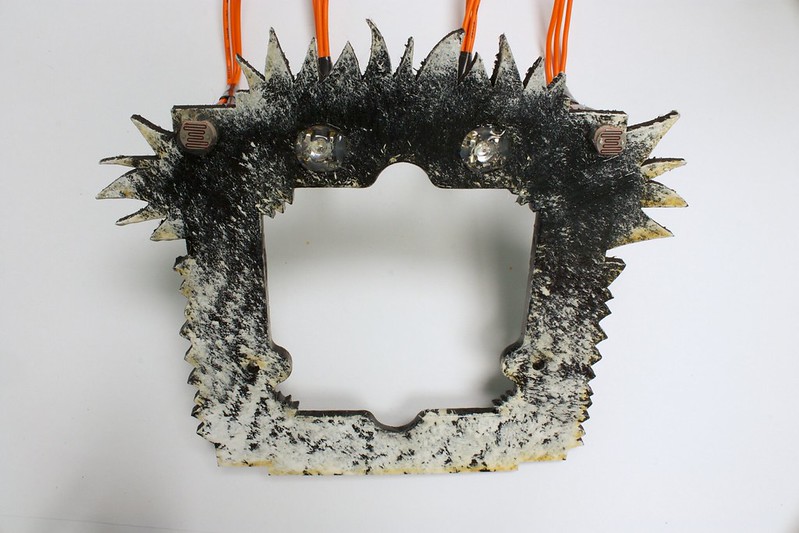
4. Tug and press the LEDs to make sure they won't fall out. No one wants a RoboBrrd with a missing eye!
5. Looks similar to how we started, but more secure. Done!


 Store
Store Robots
 Learn
Learn Community