Soldering - Step 15
Shorting blocks & Chip
Time to add on the shorting blocks and insert the chip. The point of the shorting blocks is to be able to control which power source is used for the microcontroller and servos. For example, if you want the brain to be powered by a battery pack rather than usb, then you can switch it to do so. Or, if you want the servos to be powered externally rather than usb, you can switch it to that as well.
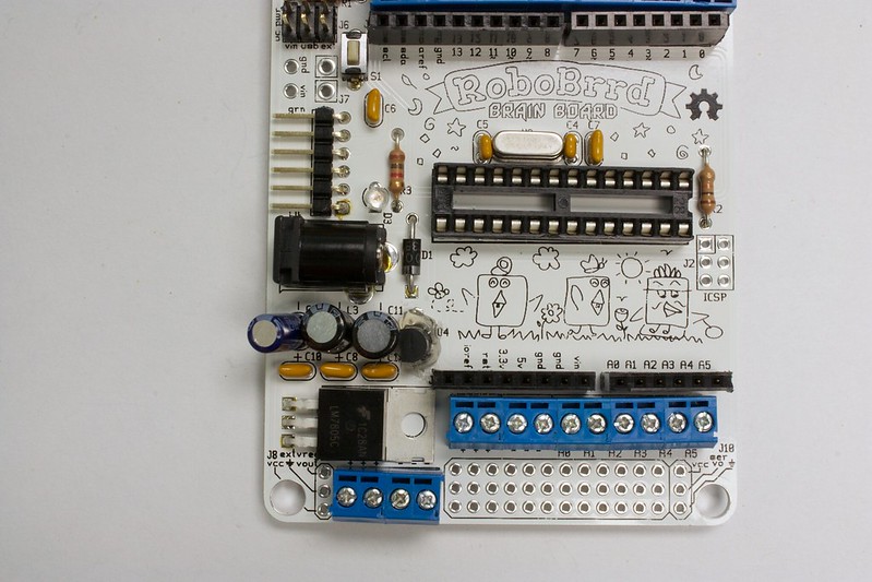
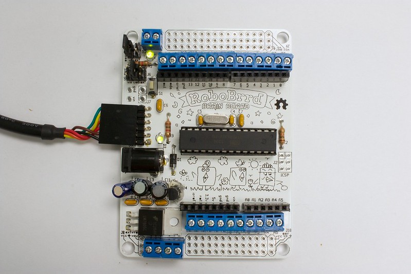
The first shorting block goes on J6, controlling the microcontroller power. Place it on the 'usb' option (middle) so that it is parallel with the left & right edges of the board. See photo #2 for illustration.
The second shorting block goes on J11, controlling the servo power. Place it on the 'uC' option (left), again parallel with the left & right edges of the board.
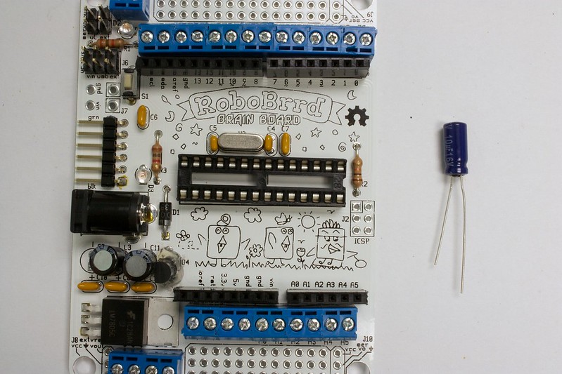
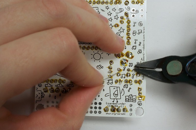
The chip (ATmega328-PU) is bootloaded with Arduino on it, running a basic 'blink' program. The legs of the chip may be splayed, so you have to gently bend them inwards so they are at a 90 degree angle. The best way to do this is by gently pressing it on a flat surface.
It's really important to be gentle. Bending them will make it much easier to insert into the socket.
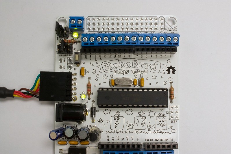
When inserting it into the socket, make sure the semi-circle half-moon indentation is on the right hand side. It should match the socket and the silkscreen. When you press it into the socket, it shouldn't be a difficult task. If it is, there may be a pin that is not cooperating and you should double check it. Make sure none of the pins get bent under the chip, or outside of the socket. ;)
Finally, when it is done you can plug in the FTDI cable! The power LED will be lit, and the pin 13 LED will be blinking. If it isn't, something might be wrong. Check that you have the chip in right, the jumpers in the right position, and that everything is soldered in properly. If you still can't find it, let us know in the
forum and we can help try to fix it.
-

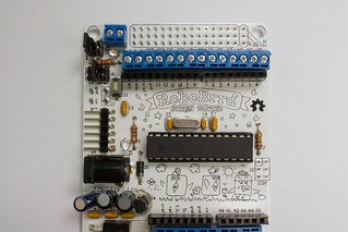
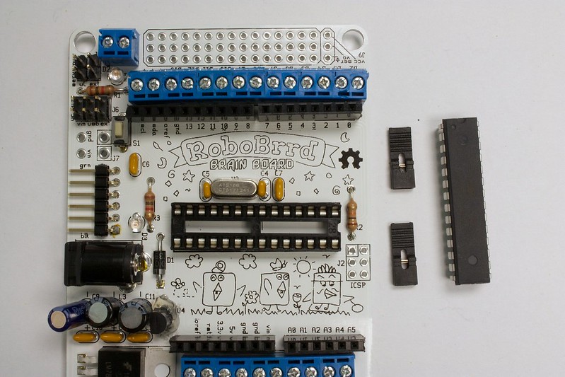
1. Grab the two shorting blocks and the chip
-
2. Place chip into the socket with the semi-circle to the right (see picture). Add the shorting blocks to J6 on uC power- usb and J11 on servo power- uC
-
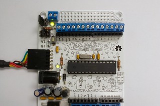
3. Plug in the FTDI connection, the power LED should light up and Pin 13 should be blinking
-
-

5. This is it! Congrats, you're done!


 Store
Store Robots
 Learn
Learn Community