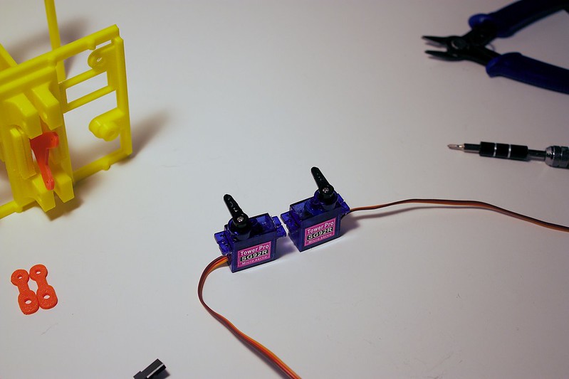
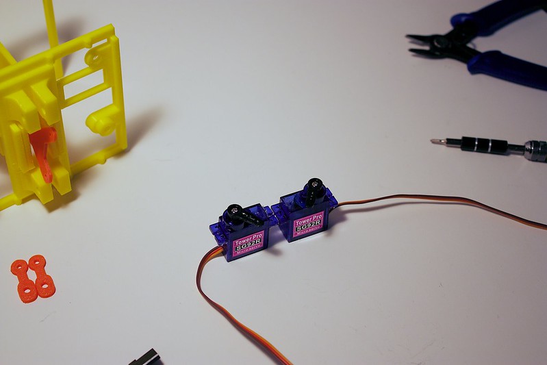
Grab two servos, and the wing servo horns.
Attach one of the small, white, plastic servo horns to the servo. Position the horn on the servos so they rotate within these boundaries. (see below photos)
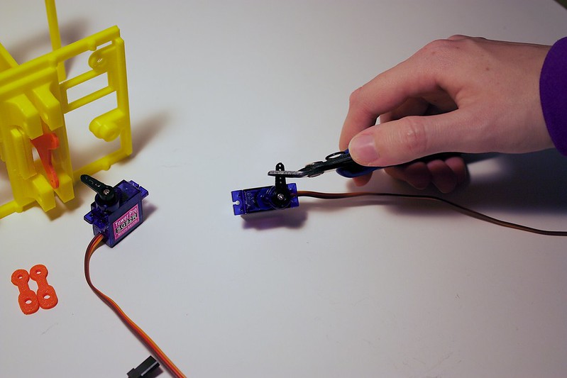
Chop the last 2 holes of the servo horn off:
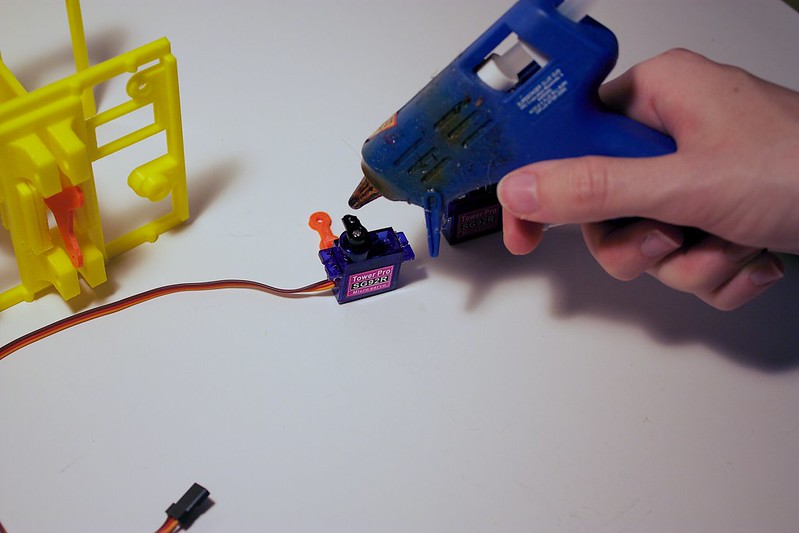
Hot glue the wing horn to the existing horn:
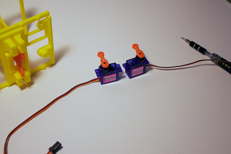
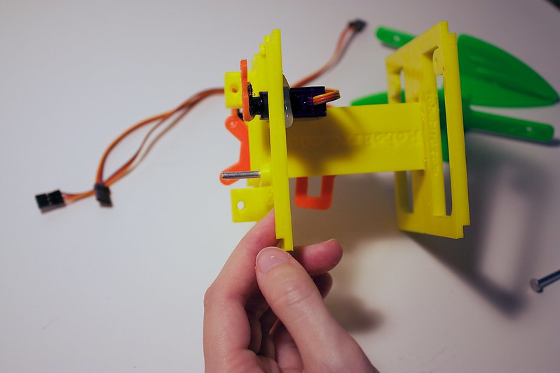
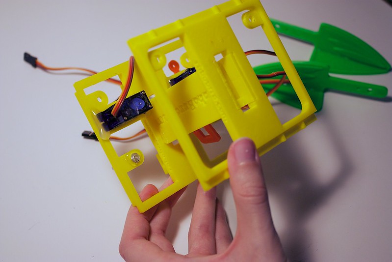
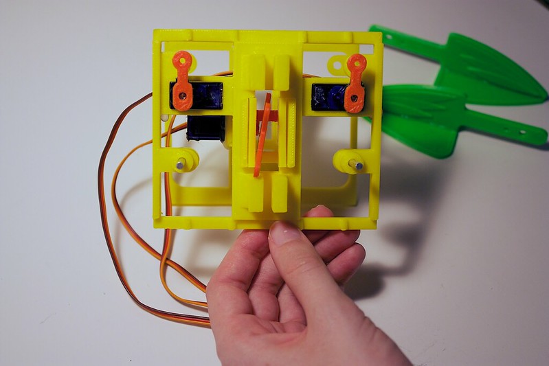
Insert the servos into the servo plate on their respective sides.
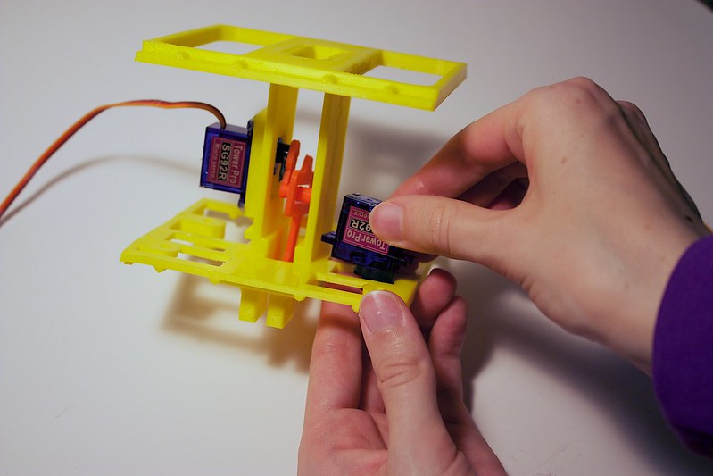
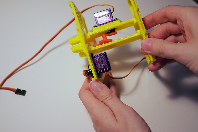
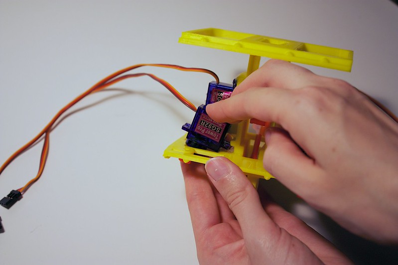
You should apply hot glue to the spots where the servo contacts the servo plate. This will secure it in place.
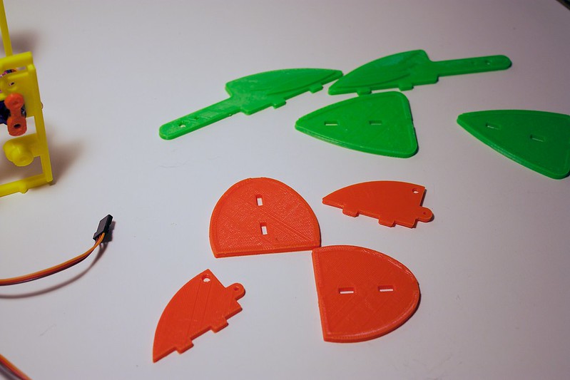
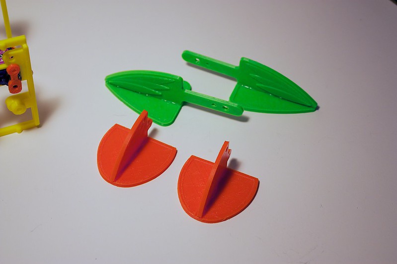
Grab both of the wing bases and wing arms. Also grab both of the beak bases and beak bridges.
For the beak, apply hot glue to the beak base in the same line as the slots.
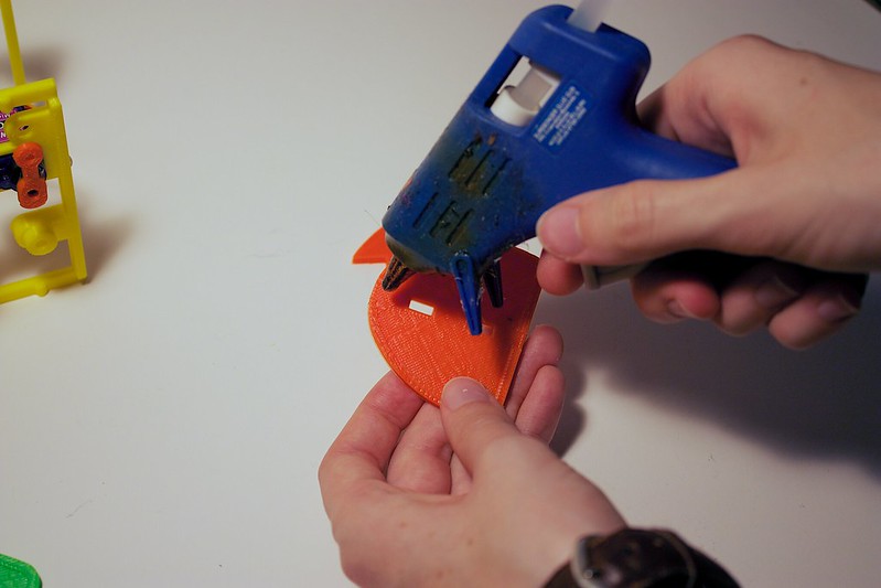
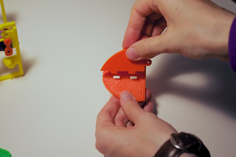
Insert the beak bridge into the slots.
The beak should have the ‘point’ of the beak bridge going towards the top of the arc of the beak base.
Repeat for the other beak.
Now for the wing! Apply hot glue to the wing base in the same line as the slots.
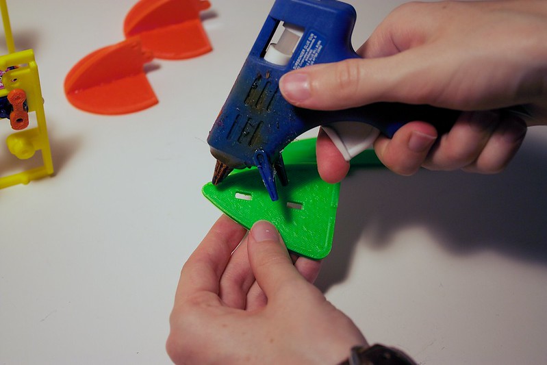
Insert the wing arm into the slots.
The wing should have the point of the wing arm going towards the point of the wing base.

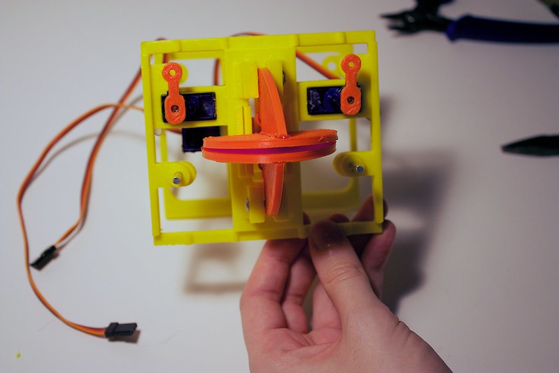
Here are the completed beaks and wings:
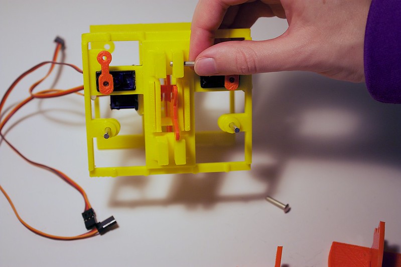
Grab the two 1” rivets.
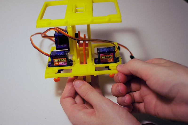
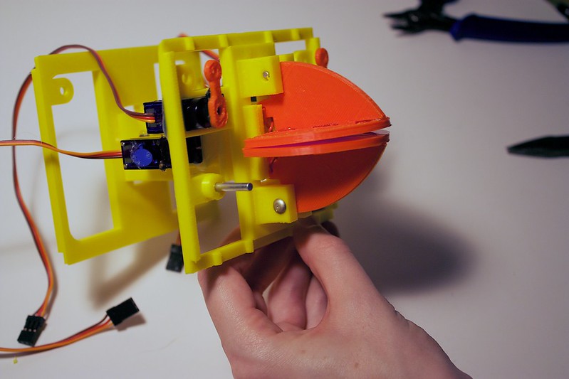
Looking at the back (glossy) side of the servo plate, insert the rivets through the hole below the servo.
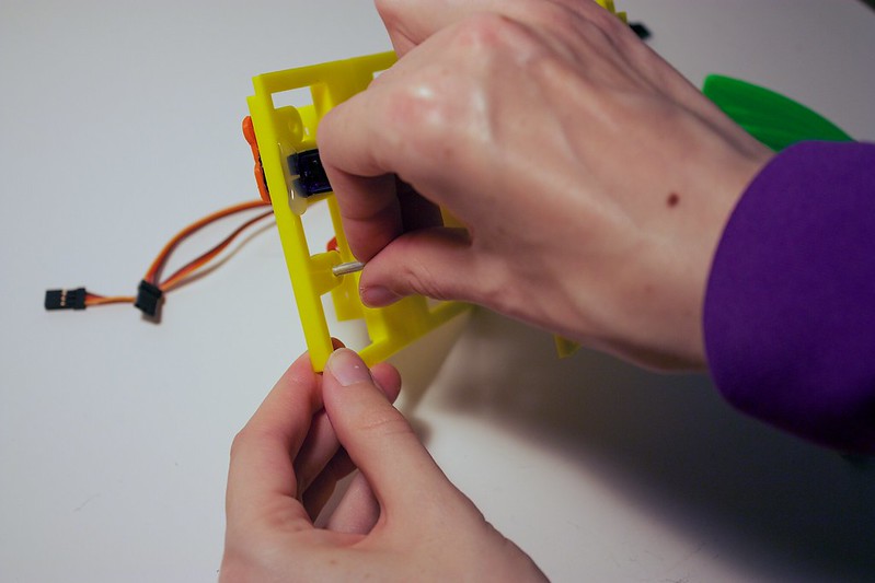
The head of the rivet should be flush with the back of the servo plate, and should extend outwards.
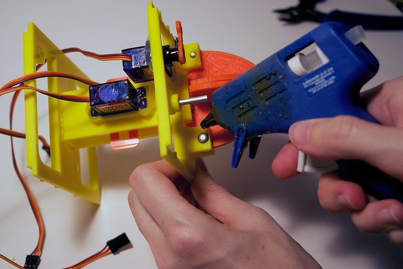
Add hot glue around the perimeter of the head so it can stay stuck to the servo plate.
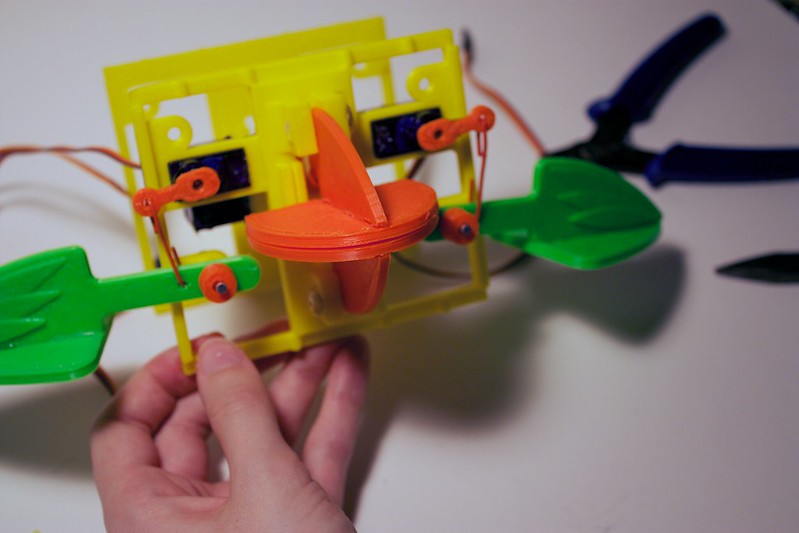
Here is the front view:
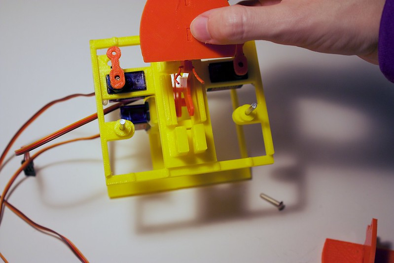
Grab the two 1/2" rivets, the beaks, and the two paper clips.
Looking at the side of the servo plate, insert the beak between the two extending tabs.
Make sure the beaks are oriented properly... otherwise this would make for one awkward birdy.
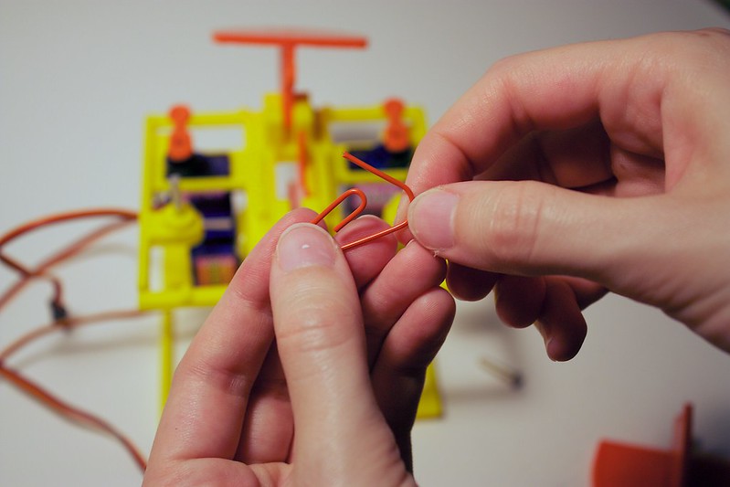
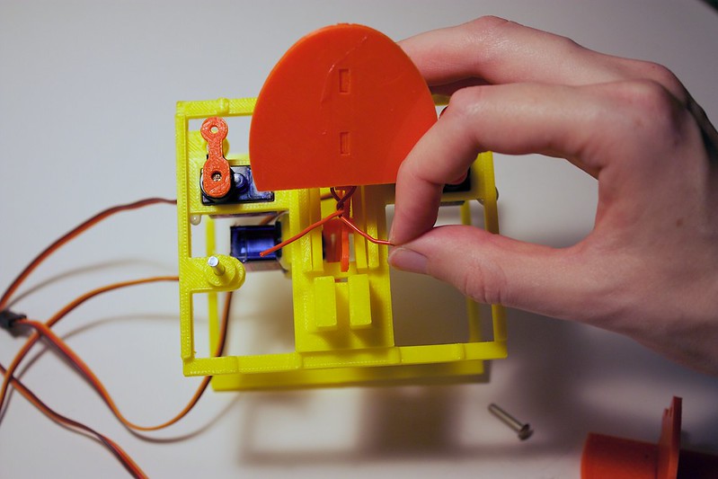
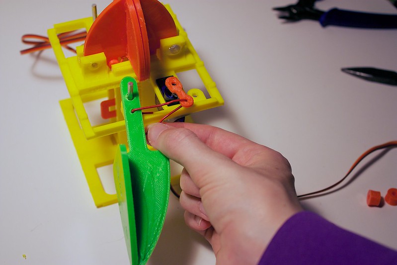
Undo the paperclip so it is a straight line.
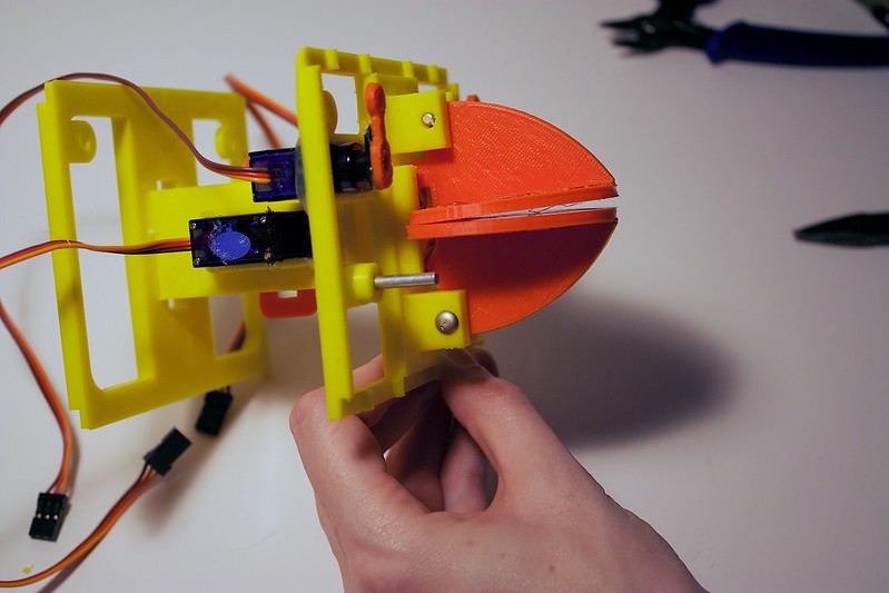
Fish the paperclip through the hole on the beak (this is a smaller hole than the hole that the rivet went through).
Then fish the paperclip through the corresponding hole on the yoke piece.
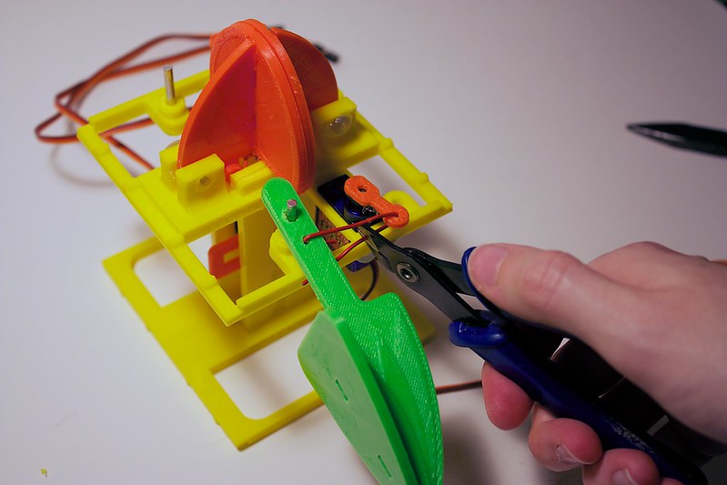
Bend the paperclip arms down. Then twist them together a few turns. Cut off the excess with your snippers (be careful).
Add hot glue around the perimeter of the rivet heads, so it can stay stuck to the tabs on the servo plate.
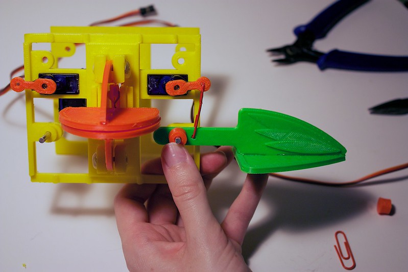
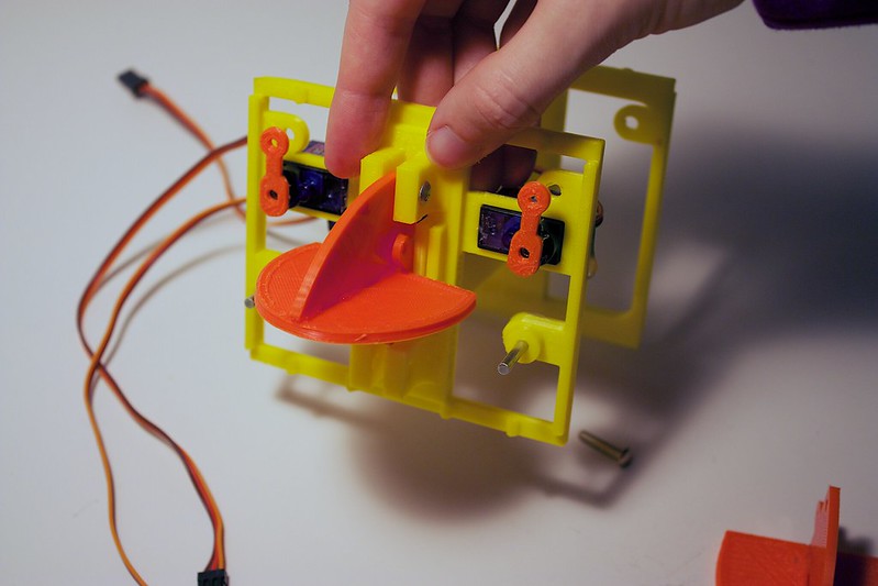
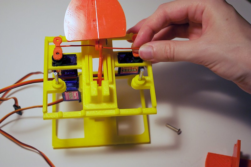
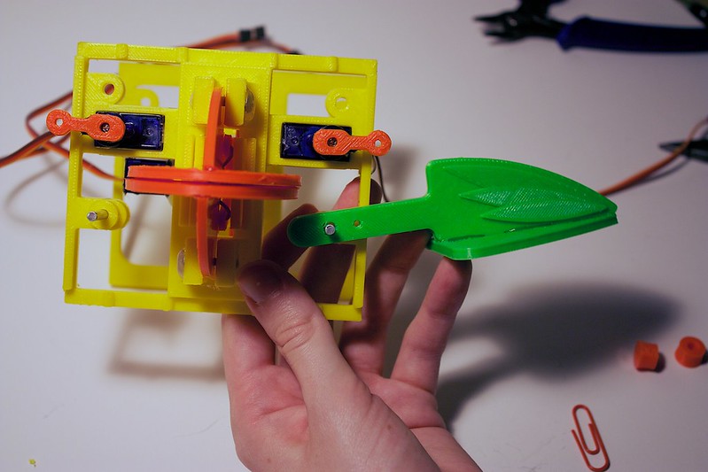
Grab the two paper clips, the washer pieces, and the wings.
Position the corresponding servo arm so that it is parallel to the bottom plate. It should be a straight line, like the horizon.
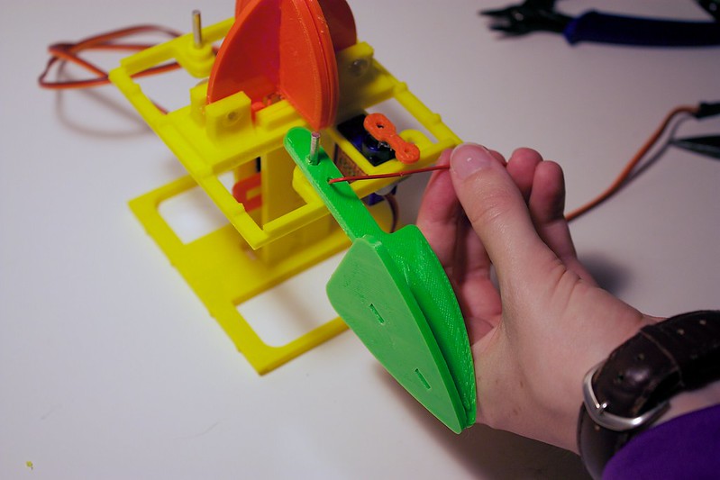
Add the wing to the rivet on the servo plate.
Undo the paperclip so it is a straight line.
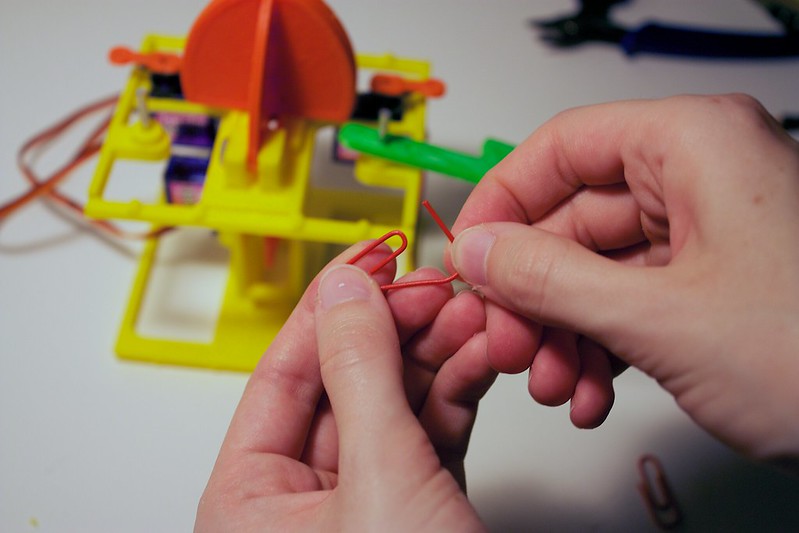
Fish the paperclip through the servo arm hole.
Then, fish the paperclip through the hole on the wing arm.
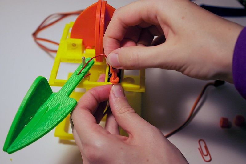
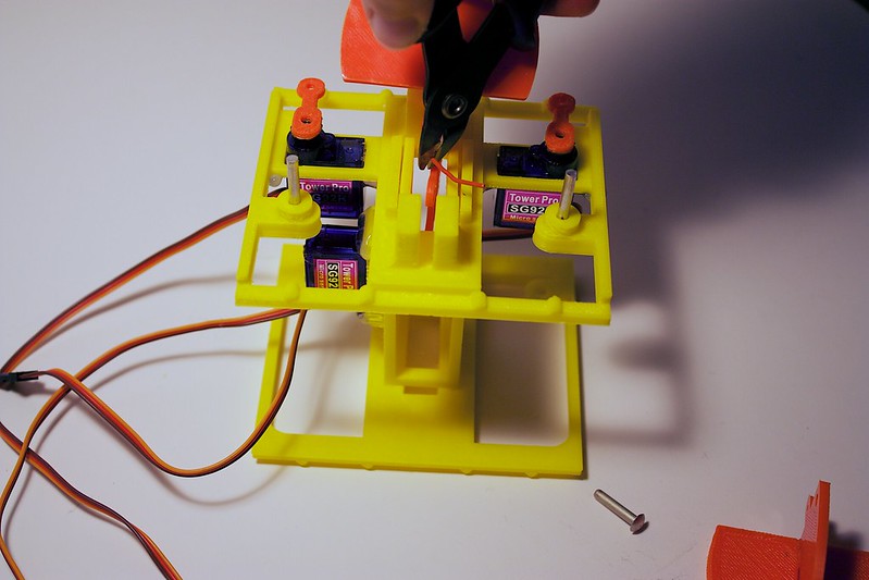
Bend backwards the excess paperclip.
Carefully trim the extra excess with wire cutters or scissors, leaving about 3mm of the paperclip that is bent backwards.
Add the washer to the rivet after the wing.