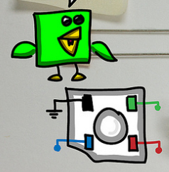
Coolios RoboBrrd: "YIPEE! Time to solder your RoboBrrd's BRAIN! It's one of the more important steps for it to conquer the wooooooorld! Bahahaha"
In the following steps we will be soldering the connections together that make the electronics of RoboBrrd work! It will require some patience, but you can do it!
In order to assemble all of the electronics, you will need some solder, soldering iron, and some wire. Having extra tools like pliers, wire cutters, third hand, are also useful.
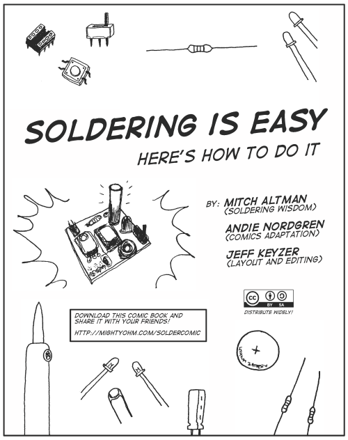
If you do not know how to solder yet, be sure to check out the Soldering is Easy! comic book.
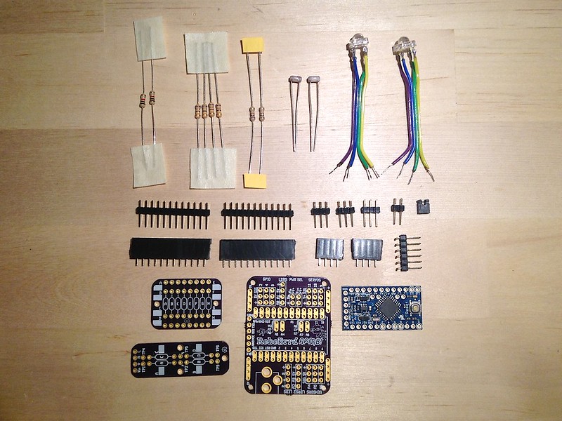
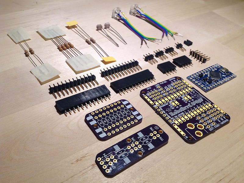
Here are all of the components that you should have in your anti-static bag.
If there is a component missing from your bag, feel free to contact us and we can try to help you.
| Quantity | Item | Place |
| 1 | Arduino Pro Mini | On RoboBrrd Brain APMB board |
| 1 | RoboBrrd APMB PCB | This is the core of the brain |
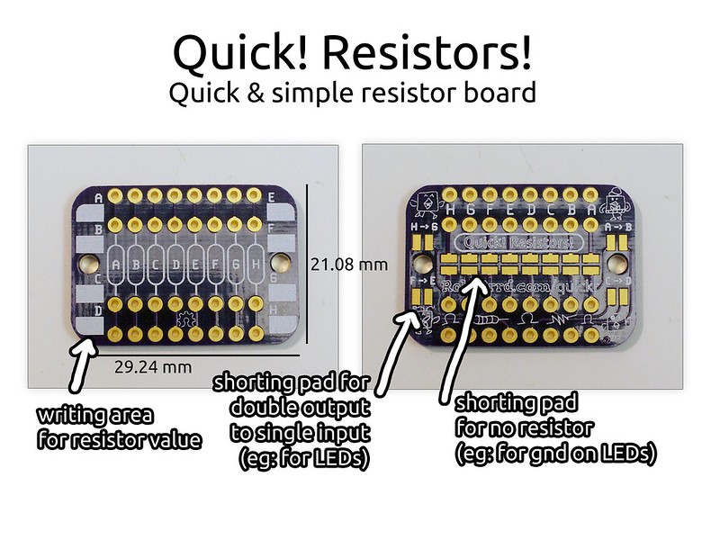
| 1 | Quick! Resistors! PCB | The RGB LEDs plug into it -- then goes to RoboBrrd APMB |
| 1 | Quick! Voltage Divider! PCB | The photocells plug into it -- then goes to RoboBrrd APMB |
| 2 | RGB Piranha LEDs | Plugs into Quick! Resistors! |
| 2 | Photocells | Plugs into Quick! Voltage Divider! |
| 2 | 1k Ohm 1/4 Watt Resistors | Pull down resistors for Quick! Voltage Divider! |
| 4 | 68 Ohm 1/4 Watt Resistors | Green & Blue LEDs for Quick! Resistors! |
| 2 | 150 Ohm 1/4 Watt Resistors | Red LEDs for Quick! Resistors! |
| 3 | 3-Male Headers | Servo headers on RoboBrrd APMB |
| 2 | 4-Female Headers | LED and LDR1 headers on RoboBrrd APMB |
| 2 | 12-Male Headers | Arduino Pro Mini |
| 2 | 12-Female Headers | Arduino Pro Mini headers on RoboBrrd APMB |
| 1 | 2-Male Header | Vcc->Vin header on RoboBrrd APMB |
| 1 | Shorting Block | On the Vcc->Vin header (on RoboBrrd APMB) |
| 1 | 6-Male 90 degree Header | FTDI header on Arduino Pro Mini |
Gather your RGB piranha LEDs, and solder wires to the leads (if this has not been done already). The length of the wire should be ~6cm.
Make sure to solder the wires in the same order on each LED. There is an angled edge on one of the corners of the LED to help match up the sides.
Looking from above, this is what colour each of the corners of the LED corresponds to.
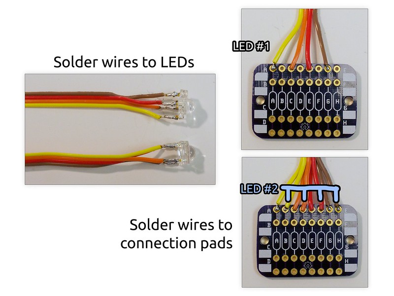
Solder the first LED to the connection pads as seen in the above photo. The wires are in this order: blue - red - Gnd - green.
Solder the second LED wires next to the first ones.
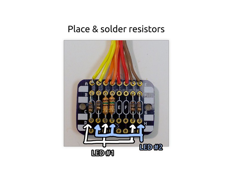
Determine the values for your resistors.
The wires that connect to the red colour on the LED need 150 ohms.
The wires that connect to the green and blue colours on the LEDs need 68 ohms.
Solder the resistors into their appropriate places for the colours, similar to as seen in the photo.