Solder the shorting pads together for the places with no resistor. This is for the Gnd connection.
Solder together the shorting pads near the edges of the board. These are for setting the output to go to a certain input. For example, so you can drive both LEDs together, in parallel.
(Page 1)
Step 4
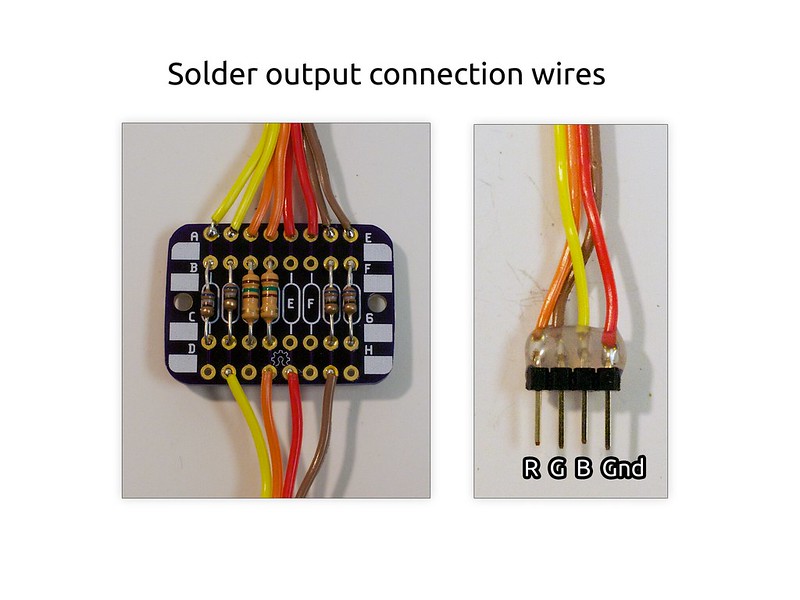
Solder the output connection wires to the bottom row of pads.
If you are adding on a male header, you can re-arrange the wires so they are R, G, B, Gnd. This will make it easier to plug into the RoboBrrd Brain (APMB).
Step 5
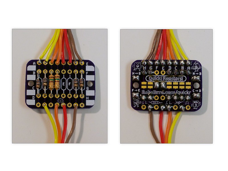
Here is what the final board looks like, front and back.
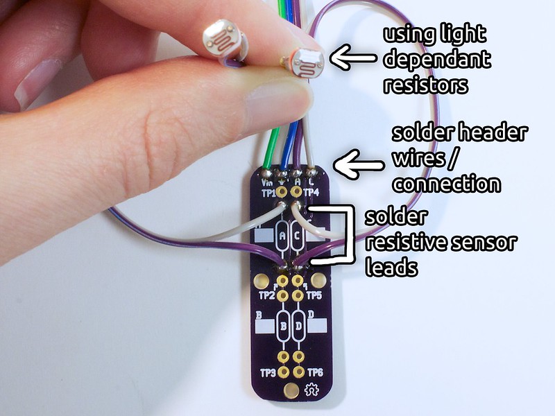
Quick! Voltage Divider!
This board adds two voltage dividers to your project. It will be used with the light dependent resistors (photocells) for RoboBrrd to sense light!
Step 6
Solder 4 wires to the header connection near the top edge of the board.
Gather your photocells, and solder some longer wires onto both leads.
Then solder these leads into the areas for resistor A and C respectively.