Programming - Overview


The RoboBrrd Brain Board is Arduino compatible, which means that you can use the Arduino IDE to program it! If you have not already, you will need to download the Arduino IDE. You can follow the instructions on the Arduino webpage on how to install the software.

You will also need an FTDI cable or adapter, like the FTDI Friend or FTDI cable.

In the following steps, we will be walking you through how to program RoboBrrd with code examples. We are assuming that you are familiar with the Arduino syntax and know how to upload the program to the board.

If this is your first time playing with an Arduino, here are some tutorials that we recommend to help you become more familiar with the environment!

Blink Test
When your RoboBrrd Brain Board is completely soldered and ready to go, a good way to test the board is by uploading the Arduino blink test program. You can find this in File > Examples > 0.1 Basics > Blink. Upload it to the board, and check that the pin 13 LED is blinking. (Here are the steps for uploading code to the board)

Tutorial Example Code
If you want to download the entire sketch of the code explained below, here it is. (However, we go through the code below so that you can learn it!) With that said, LET'S GET GOING! Open Arduino, and go File > New to start our new sketch!

Programming - Intro


For RoboBrrd, the basic code template will be structured like this:


// 1. includes

// 2. variable declarations

void setup() {

	// 3. initializing everything

}

void loop() {

	// 4. doing robobrrd actions!

}

// 5. various helper functions


Let's go through what each of these parts entails!

1. Includes - This is where we will import different libraries that we will use. We will be using the Servo library and Streaming library. Read on below for the library installation instructions.

2. Variable declarations - This is where you say what is being used and which pin number they are on

3. Initializing everything - This is where everything will be started

4. Doing robobrrd actions! - Here is where the wings will be flapping, beak opening, LEDs blinking, etc! after all the actions are completed, it repeats from the beginning

5. Various helper functions - These are functions that help with common actions, like flapping the wings, opening and closing the beak, RGB LEDs, and more

We will be going through each of these parts step by step, with plenty of examples. Although programming might seem intimidating at first, think of it this way: it's essentially magic 'commands' that you tell RoboBrrd that are formatted in a funny way so that its RoboBrrd Brain Board can understand it, and then do exactly what you have told it to! :)


Includes
Since we are using the Servo and Streaming libraries, we have to install them. Servo is installed by default, we only have to worry about Streaming. To install the Streaming library, download it here, and unpack it into your /arduino/libraries/ folder. This folder is usually located in your documents folder. Quit and re-open the IDE, and now it should be installed.

Add these two lines to the top of your program to import the Servo and Streaming library!

#include <Servo.h>
#include <Streaming.h>

Programming - Step 1

Variables

In this block of code, we are naming what is being used and what pin it is on. We are also setting some servo values, which defines how far up or down the servos can go.

// -- SERVOS -- //
// label your servo pin numbers here
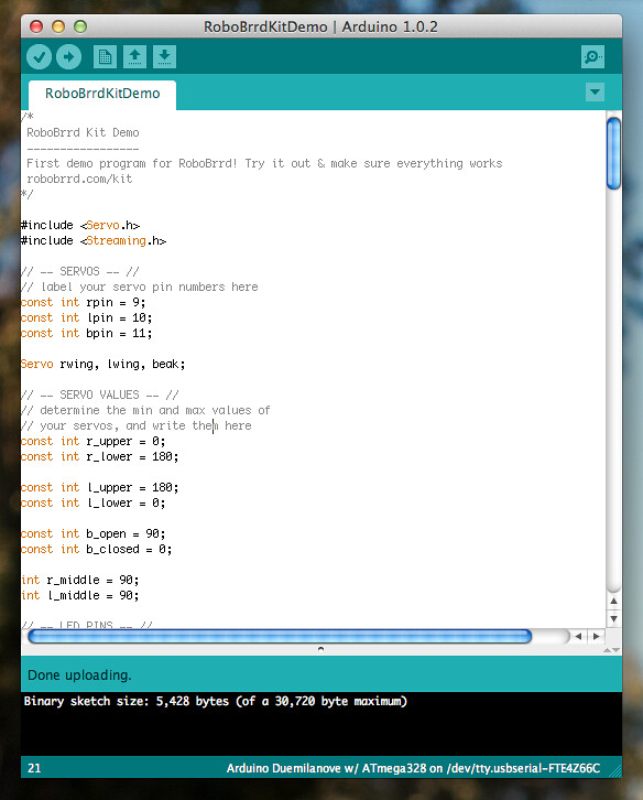
const int rpin = 8;
const int lpin = 9;
const int bpin = 10;

Servo rwing, lwing, beak;
Here is where the servo pin numbers are being set. Remember the wires that we soldered going from the headers to the pins on the back of the Brain Board? This is that. If you plug in the beak servo to the header on the left, then it will be the 11th pin.

In the code, we are calling the beak pin bpin. The const word means that the value cannot be changed anywhere else in the code. The int word means that it is an integer number, no decimals allowed.

Down on the next line, the Servo word is referring to something called an Object, which is essentially like a cookie cutter template. We need three of these for our right wing, left wing, and beak.


// -- SERVO VALUES -- //
// determine the min and max values of
// your servos, and write them here
const int r_upper = 0;
const int r_lower = 180;

const int l_upper = 180;
const int l_lower = 0;

const int b_open = 90;
const int b_closed = 0;

int r_middle = 90;
int l_middle = 90;
These are values that will tell the servos what their minimum and maximum values are. This is useful so that RoboBrrd does not hurt itself by trying to raise its wing too high, or open its beak too much. When we will calibrate the servos, we will be figuring out the precise values for these.


// -- LED PINS -- //
const int led = 13;

// the rgb pins of your servos
const int r = 3;
const int g = 5;
const int b = 6;

const int leds[] = {r, g, b};
These are the pins that the RGB LEDs are connected to, as well as the pin 13 LED. We also create an array called 'leds' for the RGB LEDs, which will have the pin numbers inside of that array. We are giving the basic example here of putting both the left and right side of LEDs on the same pins. Also notice, these pins have PWM, so we can fade the eyes. Later on, if you want to control both sides of the eyes, you can go back and customize the definitions to do that.


// -- MISC -- //
const int spkr = 7;
const int ldrL = A0;
const int ldrR = A1;
const int tmp = A2;
Here is just some extra stuff that we need, like the speaker, photocells, and the TMP36. The reason why the ldrs and tmp have an 'A' before their pin number is to signify that it is on the Analog Input.

That's it for this block of code. These snippets go at the top of the program, below the #include lines. Next up we have to initialize everything!

Programming - Step 2

Initializing in setup()

Here is where we will tell the various things we created variables for what to do. This is all in the setup() function, let's take a look!

// -- LET'S GO! :) -- //
void setup() {

	// -- serial
	Serial.begin(9600);
	Serial << "Hello from RoboBrrd! SQUAWK! CHIRP! Beginning initialization... beep beep" << endl;
Here we start off the initialization by starting up our Serial connection. The 9600 is the baud rate. It's not very fast, but the speed does not matter at this stage anyway. We will also print out a hello to the serial console! In this case the << characters are overloaded, and the Streaming library handles the call to Serial.print() (you may have seen it this way in other tutorials online). This overloading way comes in handy with lots of variables, as we will see below!


        // -- servos
	rwing.attach(rpin);
	lwing.attach(lpin);
	beak.attach(bpin); 
	
	rwing.write(r_middle);
	lwing.write(l_middle);
	beak.write(b_closed);
Now we attach the servo pins to our Servo objects. This is a function provided to us from the Servo library. Next, we set their initial 'home' positions by telling the servo to write the middle position.


        // -- leds
	pinMode(led, OUTPUT);
	blinkLed(led, 5, 100);
	
	for(int i=0; i<3; i++) {
		pinMode(leds[i], OUTPUT);
		analogWrite(leds[i], 128);
	}
Now we will set our LEDs to output, and also test fire them! For the first LED, we use a helper function called 'blinkLed' to blink it, which we will be defining below. The RGB LEDs are handled inside of the for loop. Inside of the for loop, we set the LED to output, and turn it on the medium brightness.

A for loop is a way of doing something for a certain number of times. You can set special conditions on this 'doing something', such as what it starts at, how much it goes up by each turn, and when it should stop. In this for loop, we are starting at 0 (i=0), going until 3 (i<3), and adding 1 each time (i++, which means i+=1, or i=i+1).


        // -- misc
	pinMode(spkr, OUTPUT);
	
	for(int i=0; i<5; i++) {
		playTone(260, 70);
		playTone(280, 70);
		playTone(300, 70);
		delay(100);
	}
	
	pinMode(ldrL, INPUT);
	pinMode(ldrR, INPUT);
	pinMode(tmp, INPUT);
	
	Serial << "LDR L: " << analogRead(ldrL) << " ";
	Serial << "LDR R: " << analogRead(ldrR) << " ";
	Serial << "TMP36: " << analogRead(tmp) << endl;
	
	// -- go!
	Serial << "Finished initializing! Beep bloop boop whirrrr" << endl;

}
Time to add in the misc stuff now! First up is the speaker, we will define it as an output, then do a test melody. The way the melody works is that it plays three tones in sequence, five times -- because it is in a for loop. The tones are generated thanks to another helper function called playTone. We will be touching on this helper function in a later step.

The next are the sensors. Notice how these are not set as outputs, but rather inputs. Once we set them as an input, we can read their values! In order to do so, we will print to the Serial console what their values are.

Finally after all of that is done, we have a funny line sent to the Serial console again, signifying that the initialization is complete.

Next up, we will code in the actions for RoboBrrd to do a little dance!

Programming - Step 3

Actions in loop()

This is the BEST part of the program! It's where all the stuff happens! YEA! For now, we are just going to call some helper functions to do a demo of making RoboBrrd's servos run, LEDs blink, and sensors report data. The structure of the demo is that we will blink the LED, then do the action. Let's check it out

void loop() {
	
	// -- right wing -- //
	Serial << "--rwing--" << endl;
	blinkLed(led, 1, 500);
	
	for(int i=r_lower; i>r_upper; i--) {
		rwing.write(i);
		delay(5);
	}
	
	delay(500);
	
	for(int i=r_upper; i<r_lower; i++) {
		rwing.write(i);
		delay(5);
	}
For this part, we are testing the right wing. The first for loop moves the servo from the lower position to the upper position. For each step, it pauses 5ms. This makes the movement slow. When it is at the upper position, it waits 1/2 of a second, then returns to the lower position.


        // -- left wing -- //
	Serial << "--lwing--" << endl;
	blinkLed(led, 2, 500);

	for(int i=l_lower; i<l_upper; i--) {
		lwing.write(i);
		delay(5);
	}
	
	delay(500);
	
	for(int i=l_upper; i>l_lower; i++) {
		lwing.write(i);
		delay(5);
	}
This is the same as the block of code above, except it is for the left wing.


        // -- beak -- //
	Serial << "--beak--" << endl;
	blinkLed(led, 3, 500);
	
	for(int i=b_closed; i<b_open; i++) {
		beak.write(i);
		delay(5);
	}
	
	delay(500);
	
	for(int i=b_open; i>b_closed; i--) {
		beak.write(i);
		delay(5);
	}
Again, the same as the previous two blocks of code, but it is for the beak.


        // -- heartbeat -- //
	Serial << "--heartbeat--" << endl;
	blinkLed(led, 5, 100);
	
	
	// -- eyes -- //
	blinkLed(led, 4, 500);
	
	for(int i=0; i<3; i++) {
		for(int j=0; j<3; j++) {
			digitalWrite(leds[j], LOW);
		}
	
		digitalWrite(leds[i], HIGH);
		delay(500);
	}
	
	for(int i=0; i<255; i++) {
		for(int j=0; j<3; j++) {
			analogWrite(leds[j], i);
		}
		delay(10);
	}
The first part is a little 'heartbeat' of a blink for the LED on pin 13.

Next, we turn off all of the RGB LEDs, and then turn them on one by one. They will be lit for 1/2 of a second. Afterwards, we will fade them in and out. Fading goes from 0 to 255, with 0 being not lit, and 255 being maximum brightness.


        // -- sensors -- //
	Serial << "--sensors--" << endl;
	blinkLed(led, 5, 500);
	
	for(int i=0; i<20; i++) {
		Serial << "LDR L: " << analogRead(ldrL) << " ";
		Serial << "LDR R: " << analogRead(ldrR) << " ";
		Serial << "TMP36: " << analogRead(tmp) << endl;
		delay(50);
	}
	
}
Here is the code for the sensors. Much like the code we used at the end of setup(), except here it is inside of a for loop so that it prints out 20 readings, 50ms apart.

Programming - Step 4

Helper functions

For this demo program, we don't need too many helper functions, just one for playTone and blinkLed. These go after the closing brace of the loop() function.
// -- BLINK -- //
void blinkLed(int pin, int rep, int del) {
  
  for(int i=0; i<rep; i++) {
    digitalWrite(pin, HIGH);
    delay(del);
    digitalWrite(pin, LOW);
    delay(del);
  }
  
}
This is a handy function to blink the LED without crowding up our code. It takes a pin, how many times it should repeat the blink, and how long to delay after each blink (in ms). The way the code works is that it sets the pin to HIGH, waits the given delay, sets the pin to LOW, and waits the given delay again. This is repeated for the given number of times using the for loop.


// -- SPEAKER -- //
void playTone(int tone, int duration) {
	
	for (long i = 0; i < duration * 1000L; i += tone * 2) {
		digitalWrite(spkr, HIGH);
		delayMicroseconds(tone);
		digitalWrite(spkr, LOW);
		delayMicroseconds(tone);
	}
	
}
Here is how we can pulse the speaker to make a sound. We pass it a tone and how long the tone should be (in ms). Check out the for loop: it starts at 0, goes until how long the tone should be times 1000, and increments itself by tone*2. Inside of the for loop, we again set a pin high and low while pausing, though this time in microseconds.

The speaker is a piezo element, whenever its diaphragm vibrates, it emits a sound. By pulsing a voltage like this, its able to make a clear tone. Pretty cool!

Programming - Step 5

Run & Upload

Now for the best part- compiling the code to make sure there are no errors, and then uploading it to see it work!

  • 1. Set the Board to Arduino Duemilanove w/ATmega328 from Tools>Board
  • 2. Set the Serial Port to whatever port the Brain Board is on from Tools>Serial Port
  • 1. Press the Verify button (top left, checkmark)
  • 2. Press the Upload button (next to Verify, right arrow)
  • 2. Wait for it... Done uploading! YEA! w00t w00t!
After the code has finished uploading, observe what the RoboBrrd is doing. It should be doing everything we went over in the loop() function. If you want to look at the sensor values, you will have to open the Serial Monitor:

  • 2. Open Serial Monitor (top right, circle symbol thingy)
And it's done! Very cool! If you are adventurous, feel free to tweak some of the values! In the next step we will be calibrating the servos using the Dashboard application.

Congrats!


You are done programming the first program for RoboBrrd! Now we have to calibrate the servos and add some behaviours to RoboBrrd! Let's go calibrate!

Calibrating the Servos

"I just finished coding the first program for RoboBrrd! WOOHOO!"
RoboBrrd Kit Building I just finished coding the first program for RoboBrrd! WOOHOO! #RoboBrrd