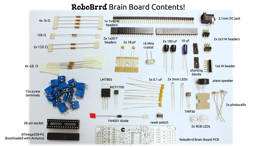
All components
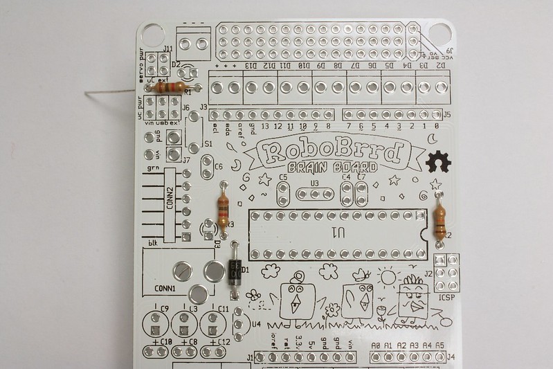
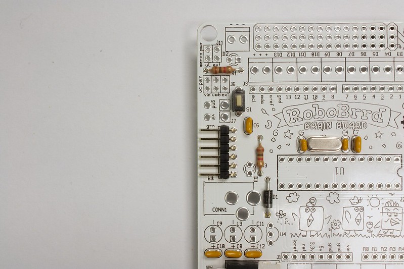
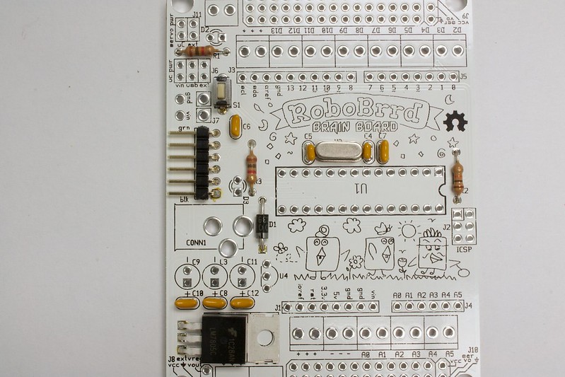
Below are listed all of the components for the RoboBrrd Brain Board and where they go on the board. For the items whose place is 'Inside RoboBrrd', we mean that it does not go on the board, but rather connected with wire and mounted inside of the chassis.
| Quantity |
Item |
Place |
| 4 |
1k Ω |
R1, R3, voltage divider w/photocells |
| 1 |
10k Ω |
R2 |
| 2 |
150 Ω |
Red leads on RGB LEDs |
| 4 |
68 Ω |
Green & blue leads on RGB LEDs |
| 15 |
Screw terminals |
Near outer edge of board (marked with the silkscreen) |
| 1 |
28 pin socket |
U1 |
| 1 |
ATmega328-PU |
Inside socket - U1 |
| 1 |
PCB |
(It's the pcb!) |
| 1 |
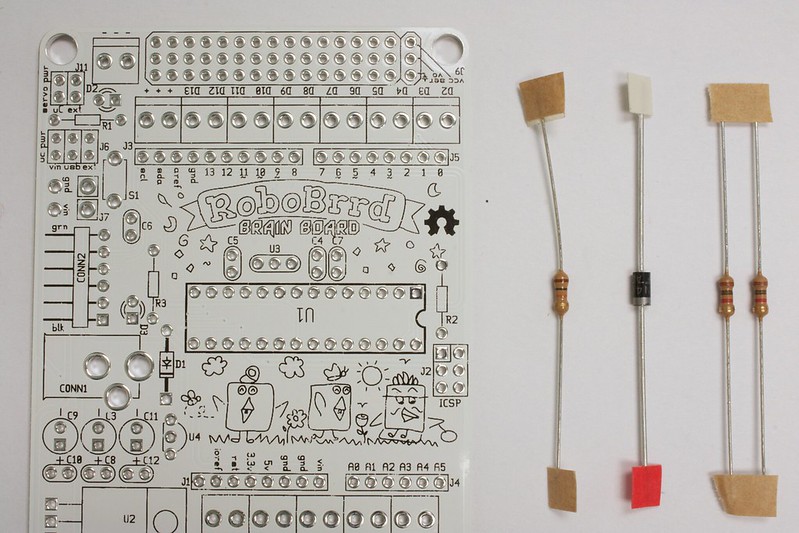
1N4001 |
D1 (band towards bottom) |
| 1 |
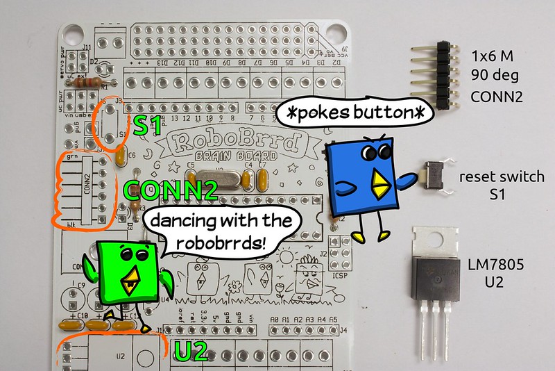
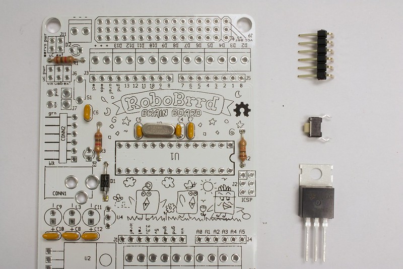
Reset switch |
S1 |
| 2 |
RGB LEDs |
Inside RoboBrrd |
| 1 |
LM7805 |
U2 |
| 1 |
MCP1700 |
U4 * |
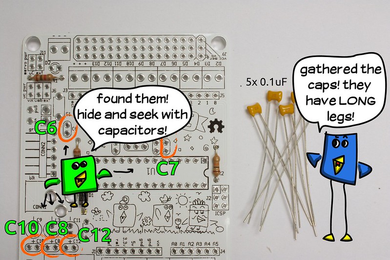
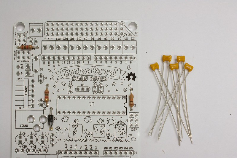
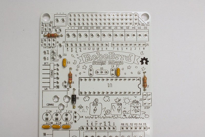
| 5 |
0.1 uF |
C6, C7, C8, C10, C12 |
| 2 |
3mm LEDs |
D3, D2 (square pad is positive) |
| 1 |
TMP36 |
Inside RoboBrrd |
| 1 |
Piezo speaker |
Inside RoboBrrd |
| 2 |
Photocells |
Inside RoboBrrd |
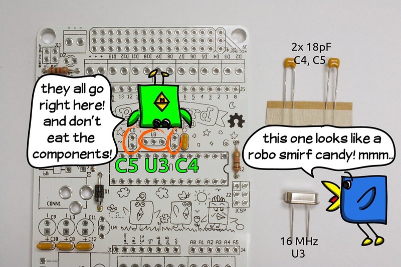
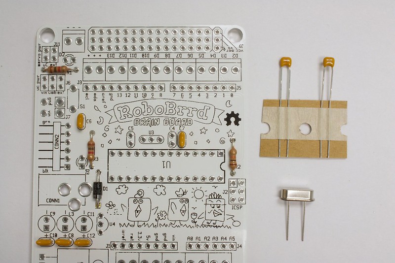
| 2 |
18 pF |
C4, C5 |
| 1 |
16 MHz Crystal |
U3 |
| 2 |
100 uF |
C3, C11 |
| 1 |
10 uF |
C9 |
| 2 |
Shorting blocks |
On J6, J11 |
| 1 |
1x6 M header |
CONN2 |
| 2 |
2x3 M headers |
J6, ICSP |
| 1 |
2.1mm DC jack |
CONN1 |
| 2 |
1x20 F headers |
J1, J3, J4, J5 (break to fit) |
| 1 |
1x40 M header |
J11, inside RoboBrrd |
* Please note that U4 (MCP1700) has its first two pins reversed on the board. We corrected the mistake by soldering it in for you, and covering the exposed leads with hot glue.
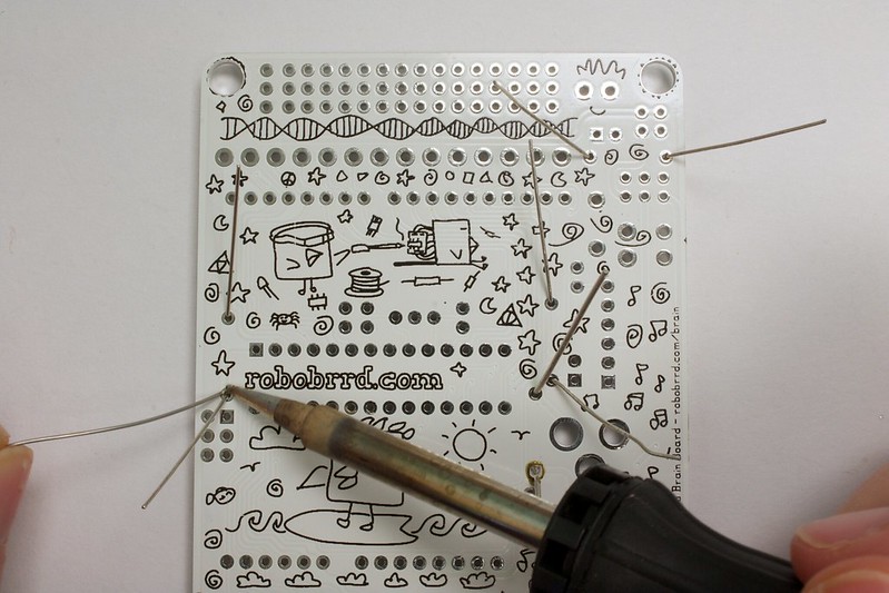
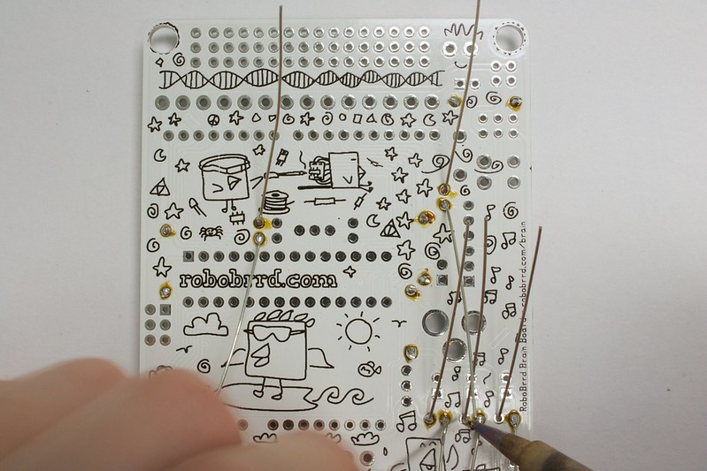
Learn Soldering
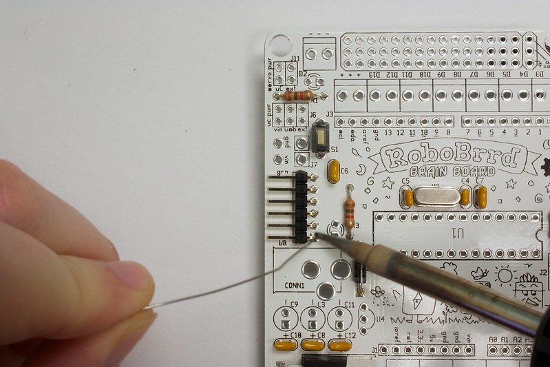
If you don't know how to solder, here are some resources that you might want to take a look at! Soldering is easy once you know how to do it, and get over the fear of holding a very hot object near your hands. :)
-
Websites
-
-
Soldering is Easy!
The coolest way to learn soldering, with a comic book! It is also translated into many different languages, check it out!
Also, if there is a
Maker Faire in your area coming up, check out the
Learn to Solder area. There will always be someone there to teach you how to solder, and you will get a cool blinky badge!
Learning to solder is like having a new trick up your sleeve! Oh yeah, and there is a
skill badge too!
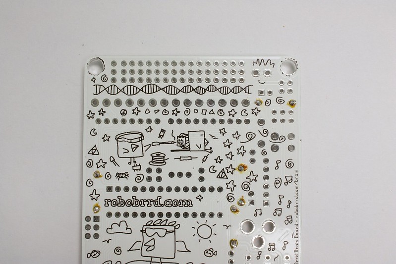
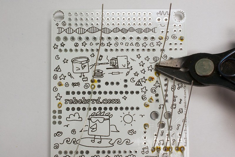
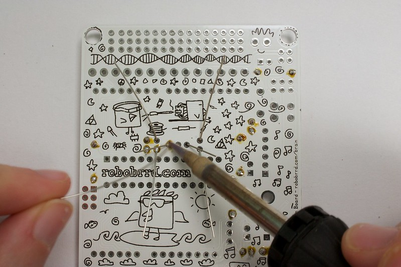
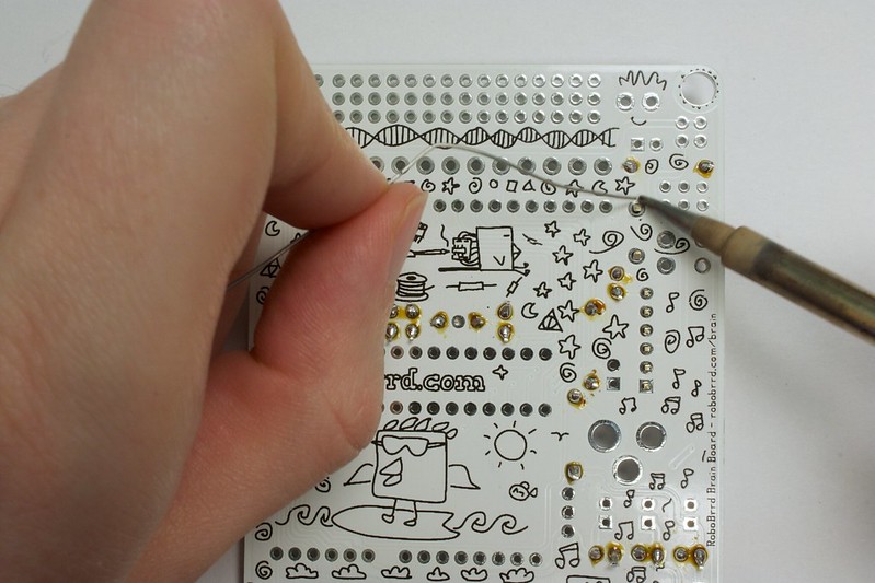
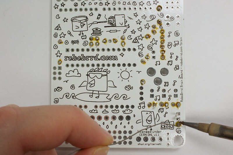
Once you know how to solder, it's important to know that for this board (and any board for that matter), if you have any cold solder joints or solder bridges (two pads connected to each other when they shouldn't be), it can lead to weird glitches and malfunctions. So always double and triple check your soldering before going on to the next step ^_^


 Store
Store Robots
 Learn
Learn Community