Soldering - Step 5

28 Pin Socket

.
This one is pretty fun since it has so many legs. When inserting it into the board, make sure the half-moon semi-circle indent is on the right hand side. The silkscreen has a corresponding indentation as well. Flip it over and bend two legs, on opposite sides and diagonal to each other. Solder these two in first, and make sure the socket is sitting flush with the board. When it is, proceed to solder the rest of the pins, and make sure that there are no cold solder joints.

  • 1. The 28 pin DIP socket
  • 2. Insert it into U1, with the semi-circle indent to the right (see picture)
  • 3. Flip board over, bend in the two end leads like so
  • 4. Solder in the two end leads, and make sure that the socket is flush with the board
  • 5. Solder the rest of the pins, make sure none of them touch eachother!
  • 6. Inspect the solder pads to make sure there isn't any cold solder joints (you can get weird bugs if there are any!)
  • 7. Flip it over, it should look like this - Done!

Soldering - Step 6

Power LED & Pin 13 LED

.
These are the two 3mm LEDs. LEDs are light emitting diodes, they are polarized so only work in one direction. The longer lead should go into the square pad. Make sure this is correct, otherwise it won't work!

  • 1. Grab the two 3mm LEDs
  • 2. Insert the first LED into D3, the longer lead goes through the square pad!
  • 3. Add the next LED to D2, long lead through square pad again!
  • 4. Solder in the LEDs, make sure to adjust them so they aren't crooked
  • 8. Cut the leads
  • 9. Flip it over, it should look like this - Done!

Soldering - Step 7

MCP1700

.
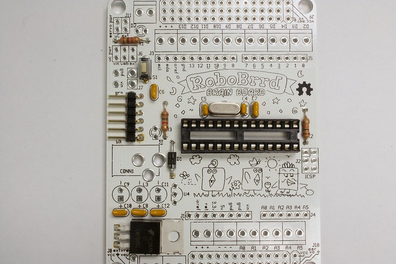
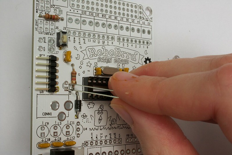
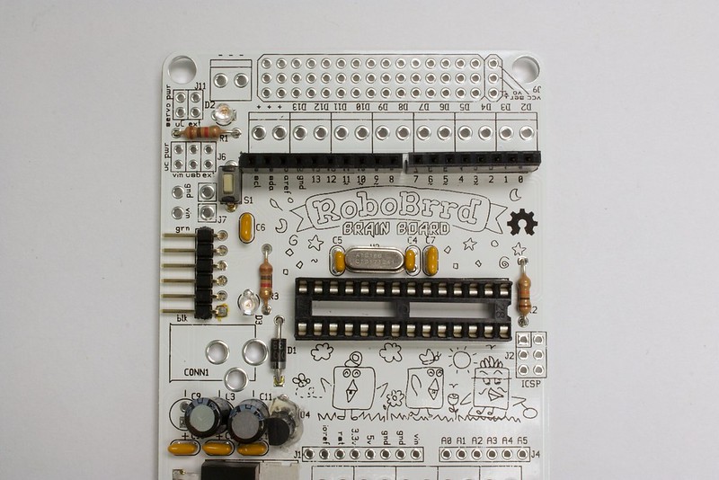
The MCP1700 is the 3.3V regulator. On some boards, this may already be soldered for you (with some hot glue). We accidentally flipped two of the pins, so they have to go criss-cross, as seen in the photos below.
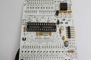
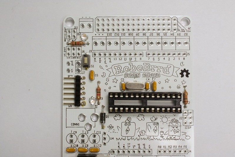
Make sure that the flat side of the component matches with the silkscreen. The flat side will be facing the left edge of the board.

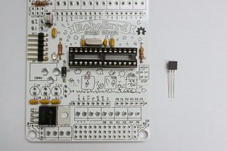
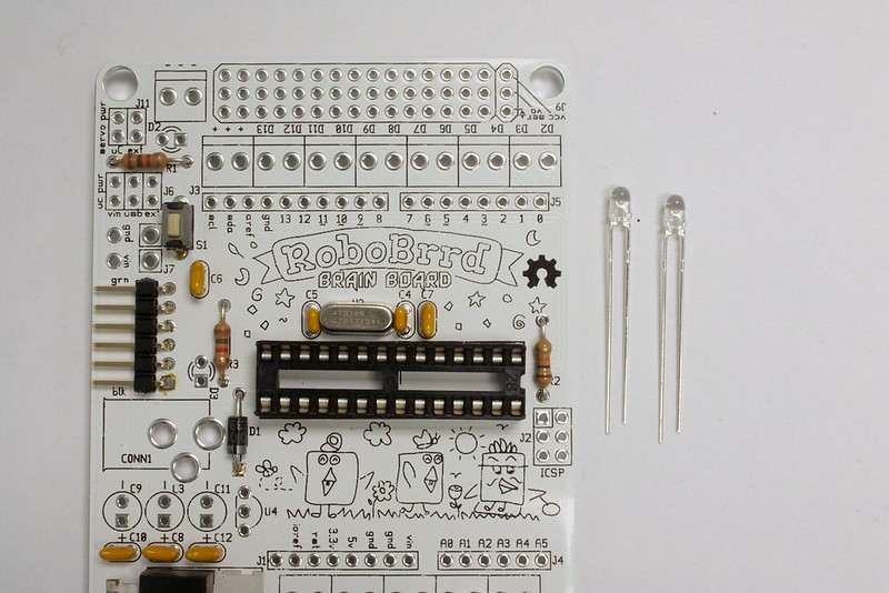
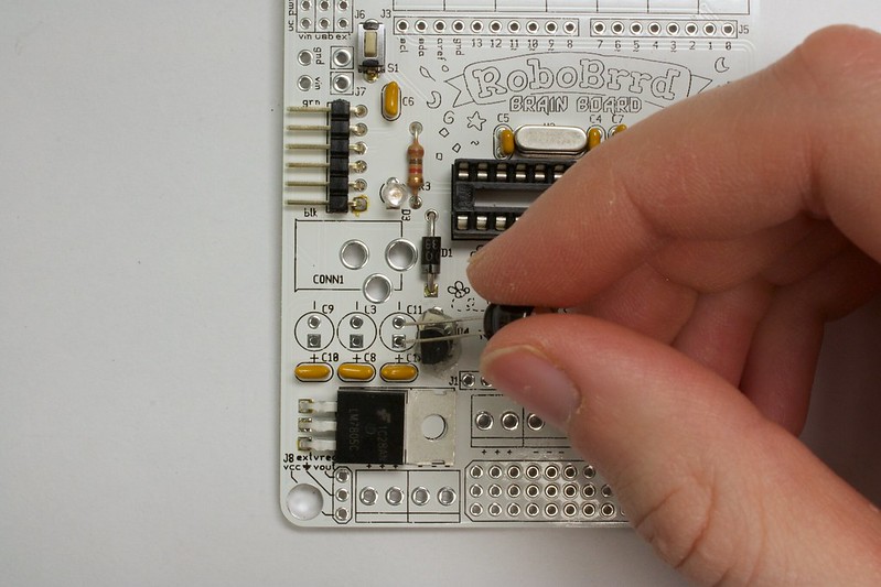
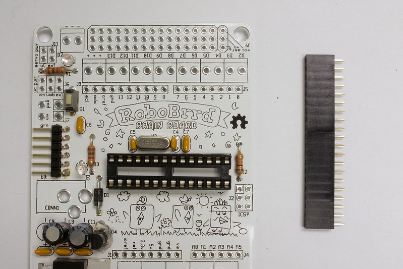
  • 1. Grab the MCP1700- be careful to not get it confused with the TMP36
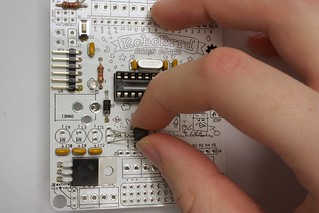
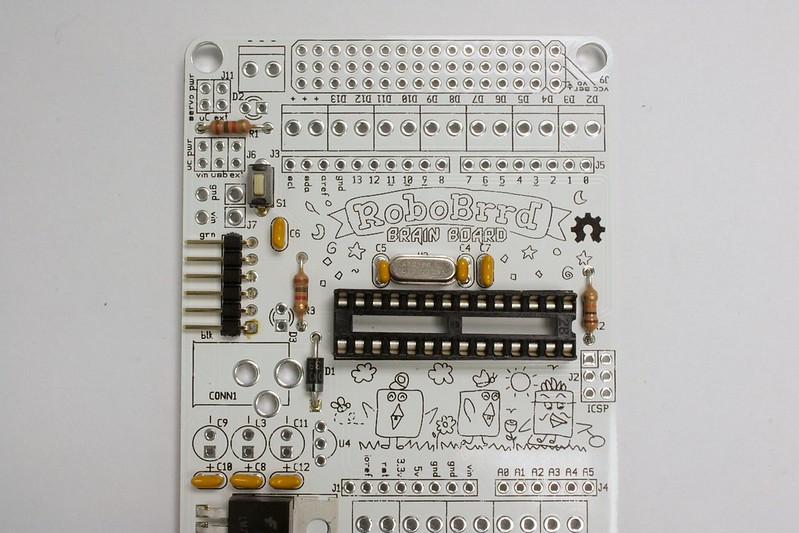
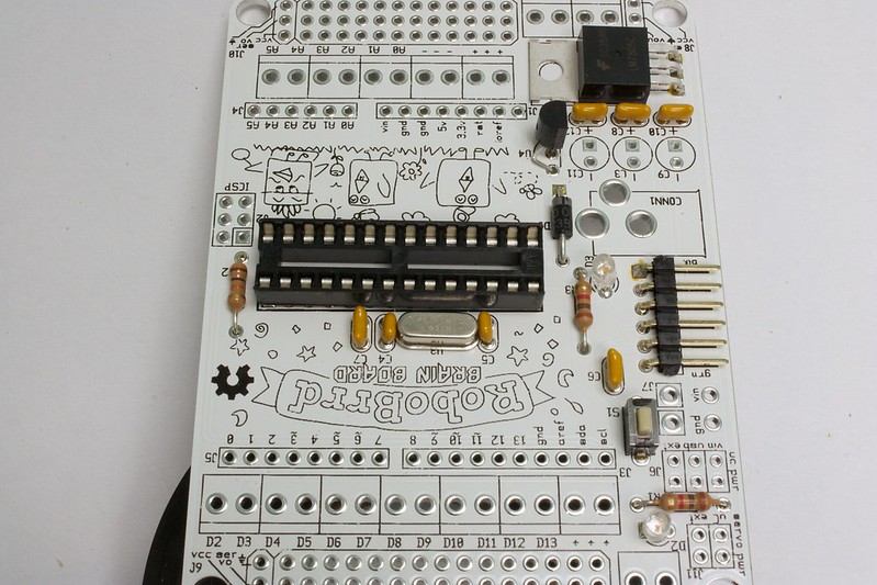
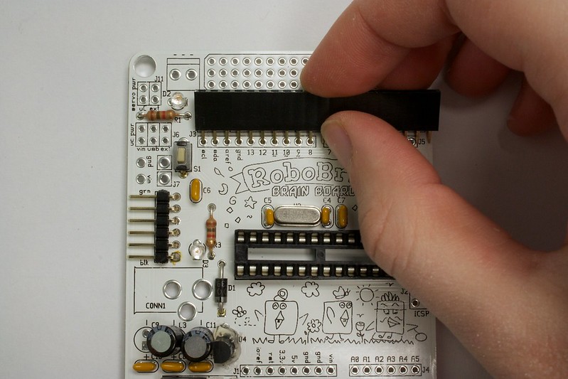
  • 2. Twist the first two leads around, and insert it into U4
  • 3. Careful that the twisted leads don't touch
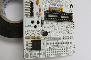
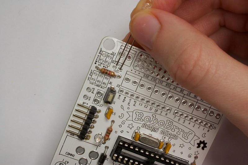
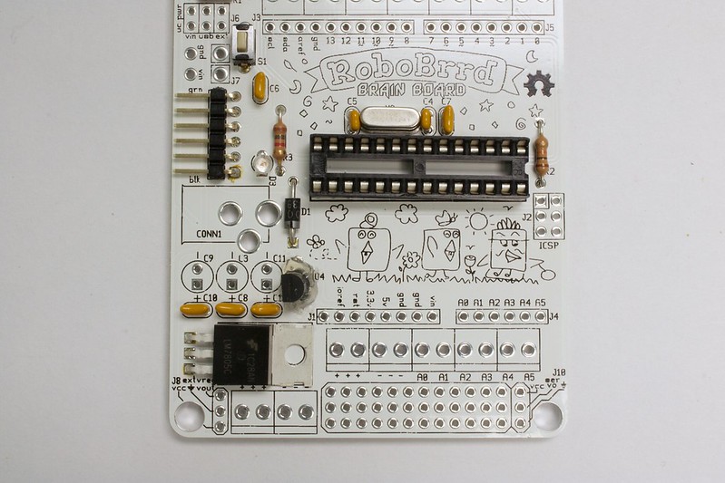
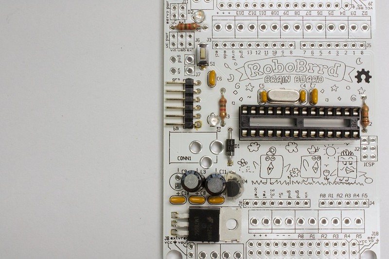
  • 4. Here's what it looks like from the other side
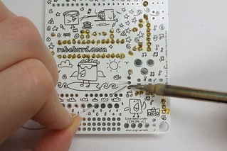
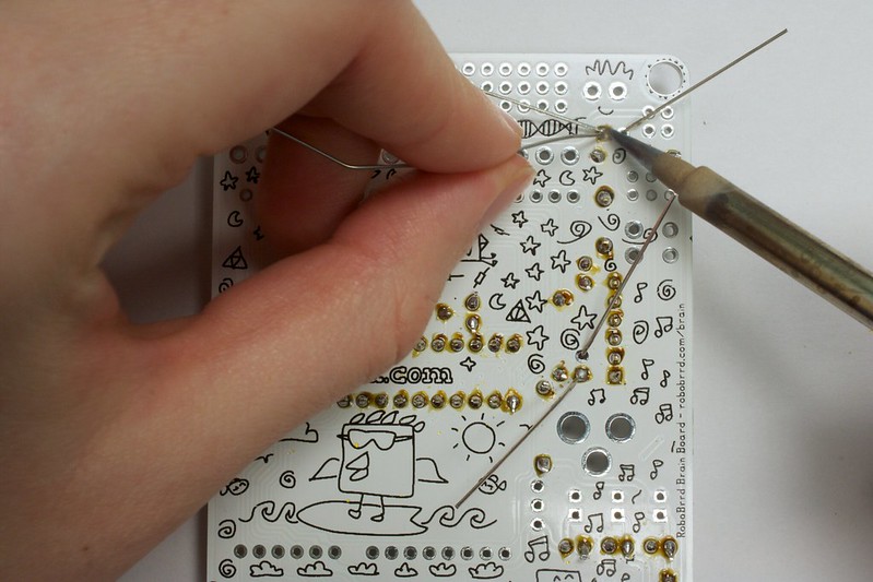
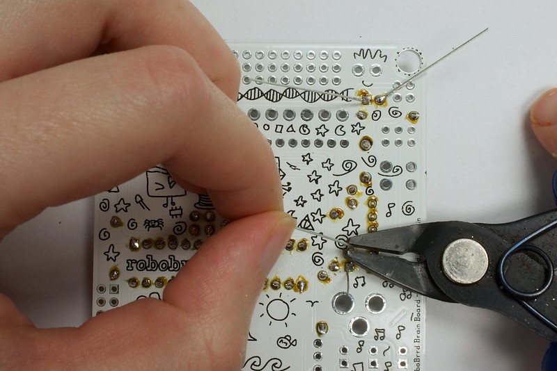
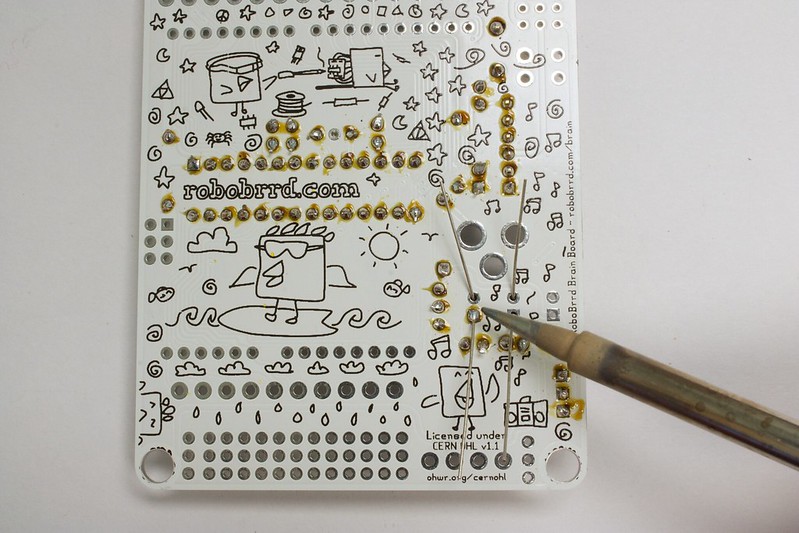
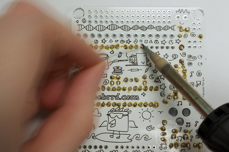
  • 5. Solder in the leads
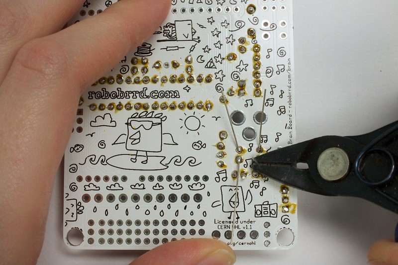
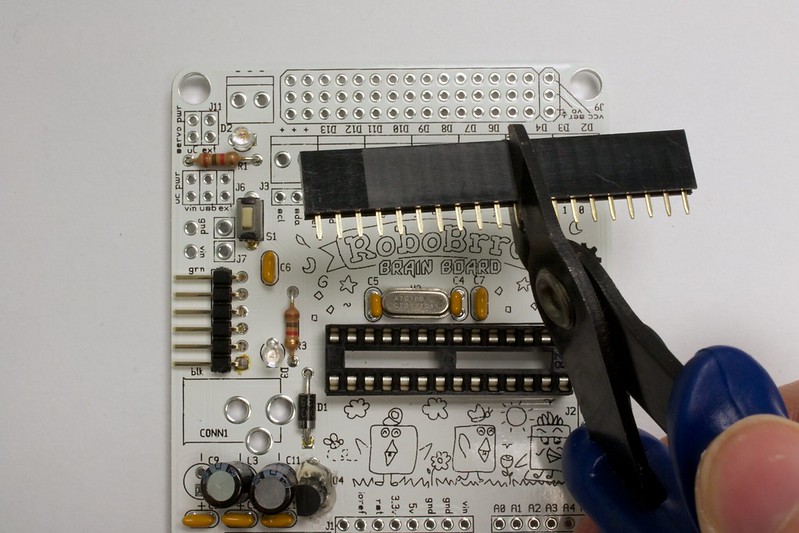
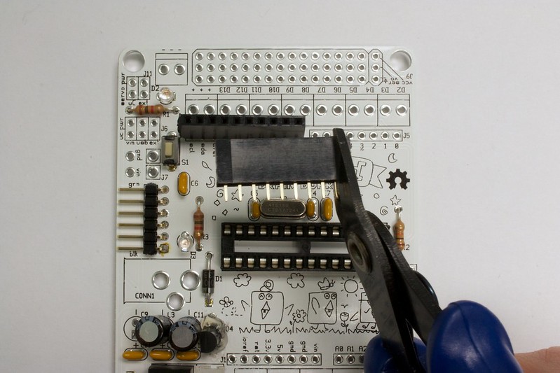
  • 6. Clip them
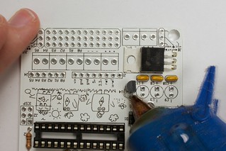
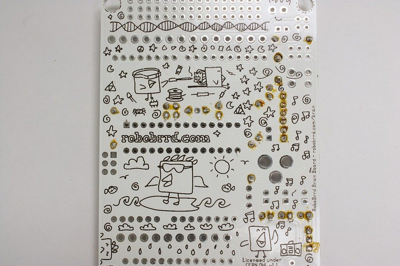
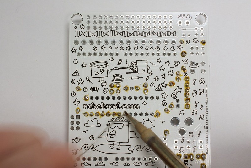
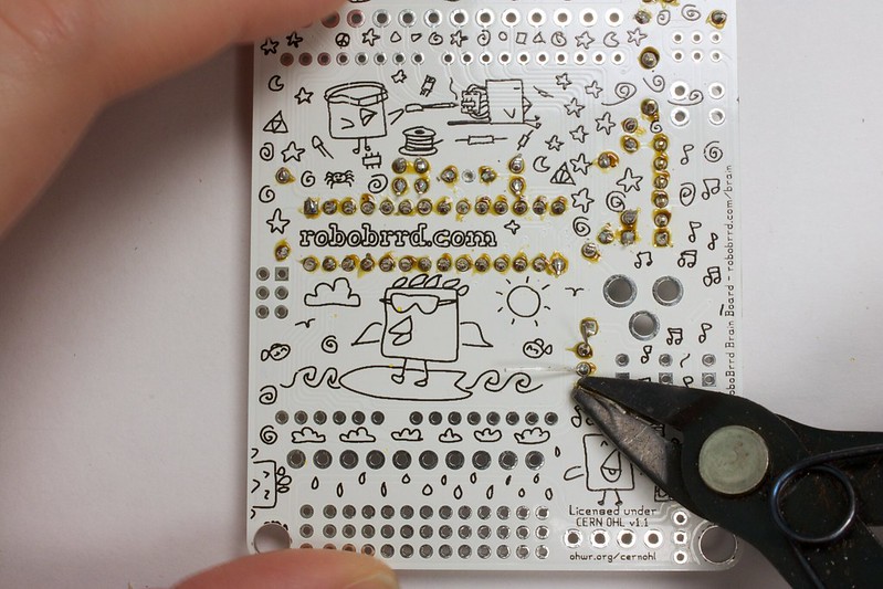
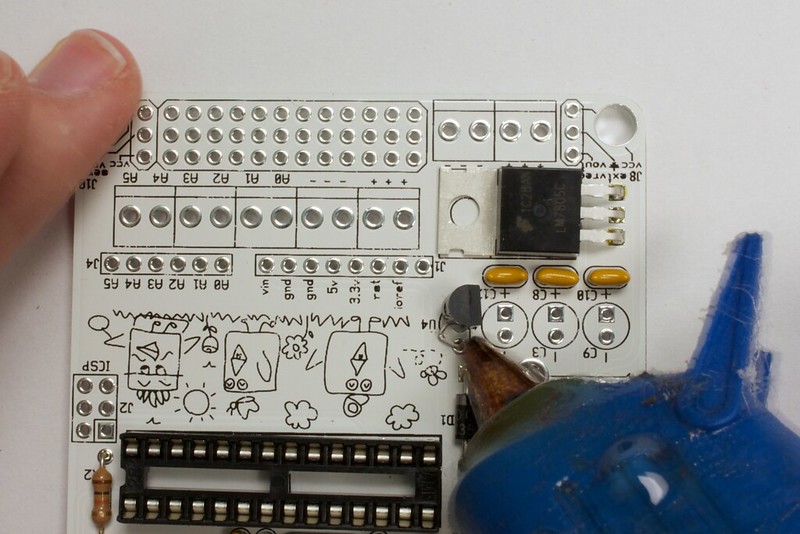
  • 7. Flip board over, and add hot glue around the exposed leads
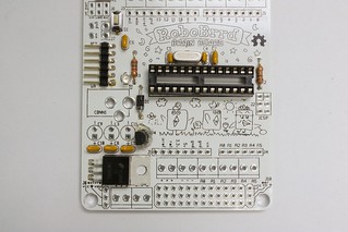
  • 8. This is what it should look like when done

Soldering - Step 8

2x 100uF Caps

.
Be sure to choose the two capacitors for this that are 100uF! They look short like the ones in the photo. These capacitors are polarized, so make sure that the long lead goes into the square pad. The minus signs on the plastic will line up with the minus sign on the silkscreen as well.

  • 1. Grab the two 100uF capacitors, that's the black ones not the blue one!
  • 2. Add the first cap to C11, longer lead goes through the square pad
  • 3. Add the second cap to C3, again longer lead goes through the square pad
  • 4. Solder in the leads
  • 5. Cut the leads
  • 6. Flip board over, this is what it should look like- done!

Soldering - Step 9

Female Headers - Top Row

.
This piece of female headers has to be broken into two separate pieces, one that is 10 pins long, and the other that is 8 pins long. The best way to cut these is to cut directly in the middle of the 11th pin for the 10 pin long piece, and with the remainder cut in the middle of the 9th pin. Cutting in the middle of the pins will destroy that pin, but that is OK! Check out the photos below to see an illustration of this description. It's important to be patient with this part and not over-power the cut.

  • 1. Grab the 1x20 F header row
  • 2. Align it with J3 and count how many pins you will need (10)
  • 3. Cut exactly in the middle of the 11th pin
  • 4. Same thing for J5, it needs 8 pins
  • 5. Cut exactly in the middle of the 9th pin
  • 6. Add headers to the board
  • 7. Add solder to the pads, make sure the headers are flush and perpendicular to the board
  • 8. Flip it back over- Done!

Next: Soldering - Part 3


There's still more components to be soldered! Keep going, on to part 2!

Soldering Part 3