Soldering - Step 13
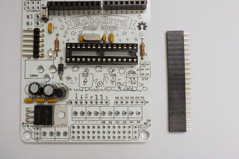
2.1mm DC Jack
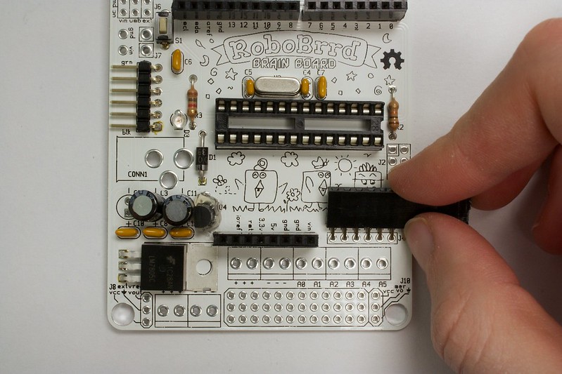
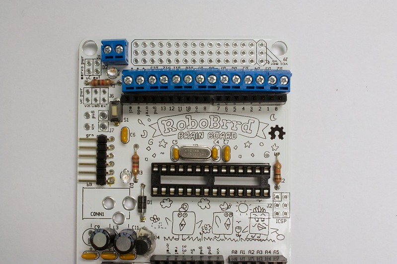
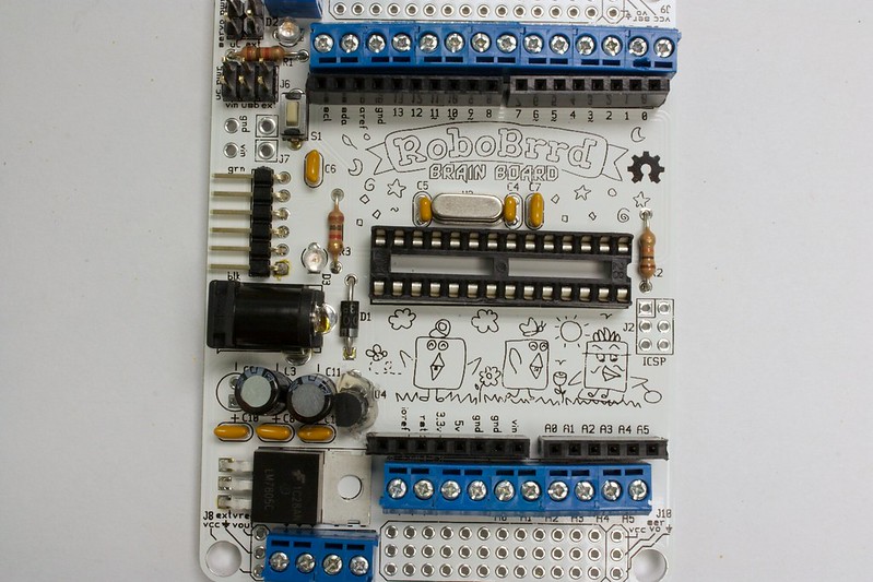
The 2.1mm DC jack is where a battery pack or transformer could be plugged in to power RoboBrrd. One of the differences between this component and the others is that the solder pad holes are quite a bit bigger. This means that more solder has to be added. Place it into CONN1. Before soldering all the pads, make sure that the jack is flush with the board. It's really tricky to fix later on! Also, be careful with the heat from all of the extra solder.
If you are wondering, the tab on the back of the connector is +V, and the other two tabs are Gnd. This means that the outside of the jack will be negative, and the inside prong will be positive. Sometimes there are different types of DC power supplies that you can get, so look for a 'positive centre'.
-
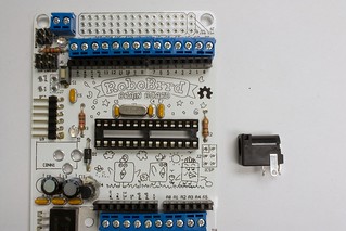
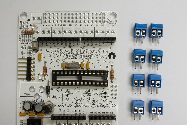
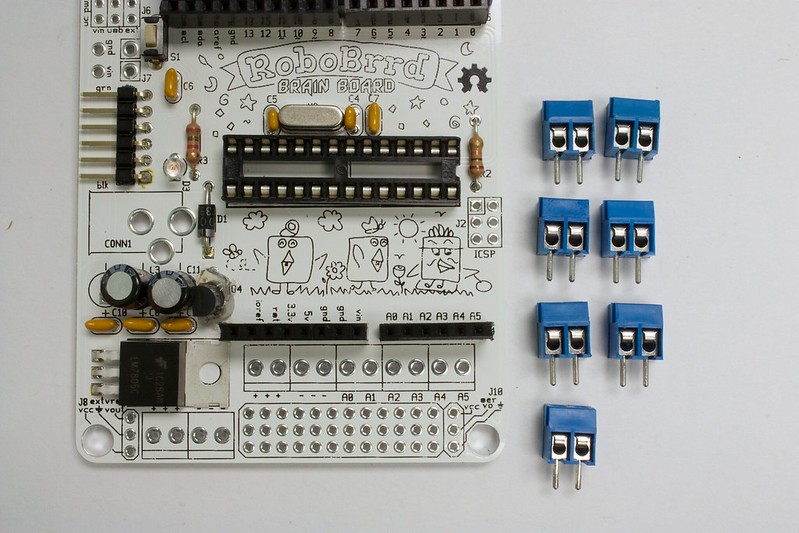
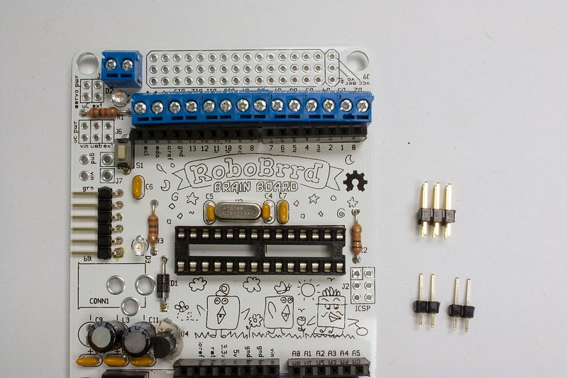
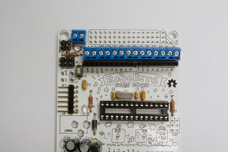
1. Grab the 2.1mm DC Jack
-
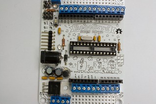
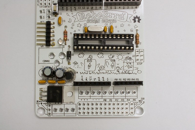
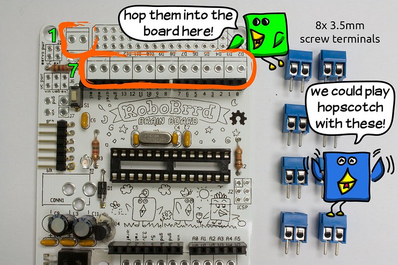
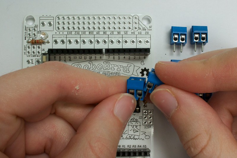
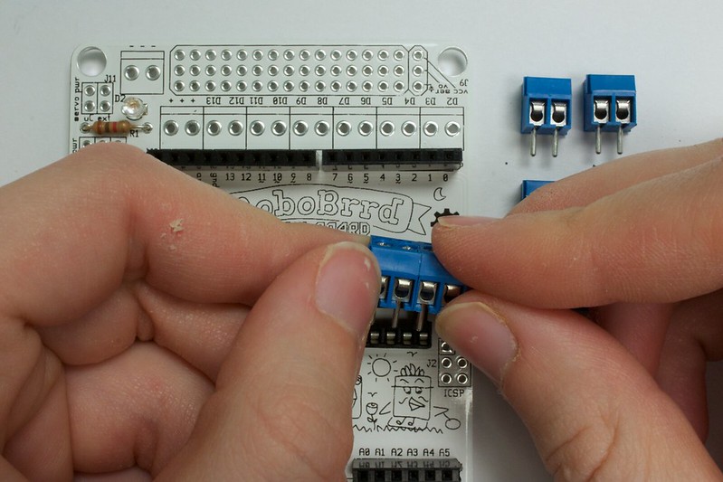
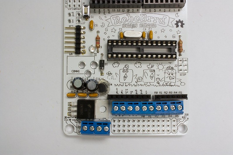
2. Insert it into the board at CONN1
-
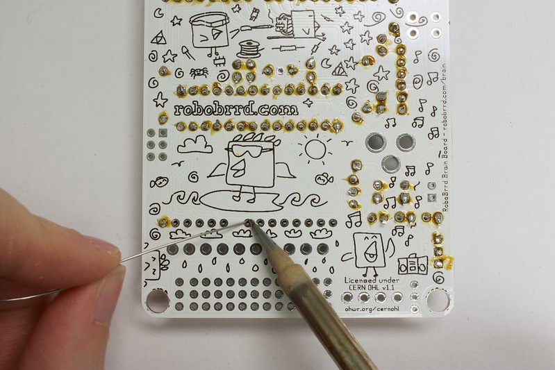
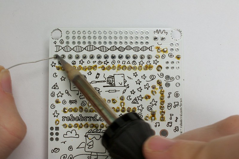
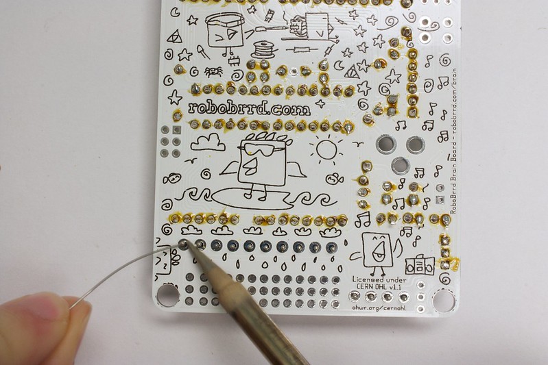
3. Add solder to the pads, you may need a bit more solder for these ones since they are bigger
-
-

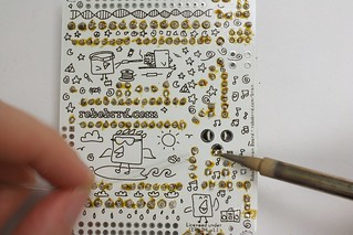
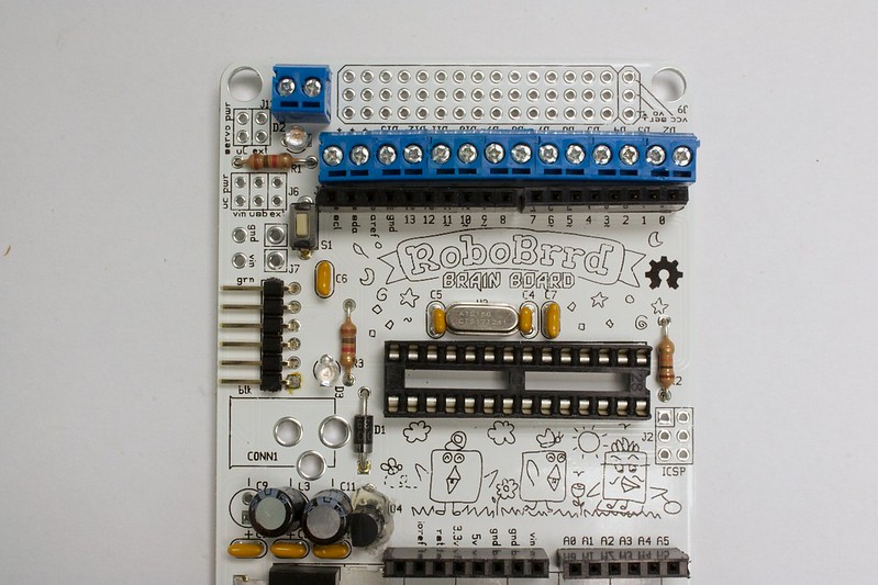
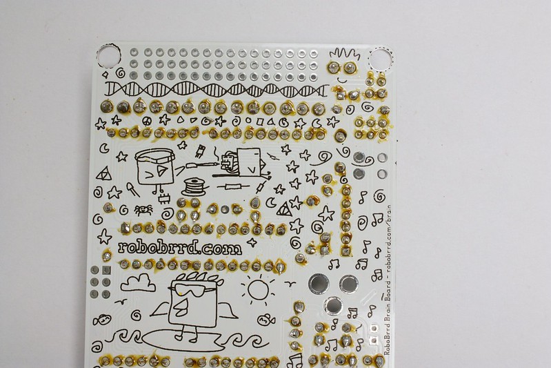
4. Flip board over, this is what it should look like - Done!


 Store
Store Robots
 Learn
Learn Community