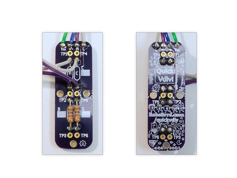
Here is what the final board looks like, front and back.
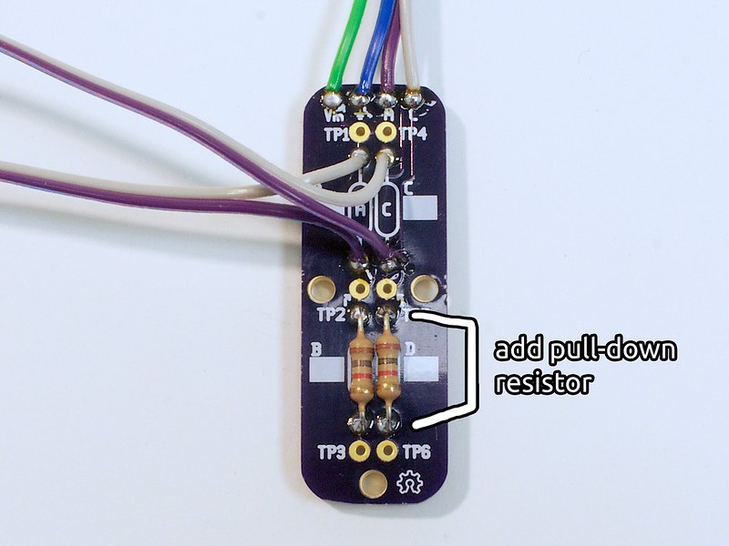
The voltage from the sensor on the left hand side will be output to the top connection labeled A. Right hand side is C.
If you want, you can solder a male header to the wires to make it easier to plug in. The order is Gnd - Vin - A - C or using the colours in the photos: Blue - Green - Purple - White.
Sorry about the order of the wires being confusing! It was a little bit of a mistake on our end.
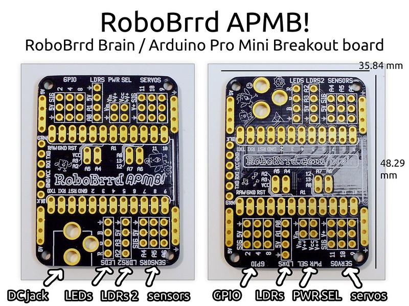
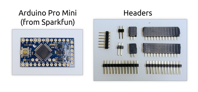
Your RoboBrrd needs a brain! We will use this Arduino Pro Mini Breakout board to get RoboBrrd up and chirping.
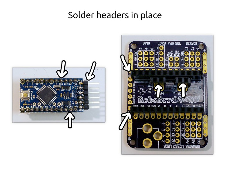
The input and output pins are clearly marked, so you will never get confused with where the servos, LEDs, and light sensors should be plugged in.
Using the Arduino Pro Mini as a ‘drop in’ controller will give you flexibility with the electronics. If you need to borrow the controller for a different project, just remove it from the RoboBrrd Brain board. When you want to control RoboBrrd again, plug the Arduino back in! Simple and effective!