Build

Intro


Welcome, beep boop, welcome! On this page we will be putting together the pieces to create our Buddy 4000 chassis. Here are some tools that will be useful for building the chassis.

Tools Required
- Screwdriver
- Super glue
- Hot glue
- Sand paper / file

Here is an overview of Buddy 4000 to familiarize yourself with all the pieces.


Below you will find a table with all of the pieces. Afterwards, there are steps with helpful images that you can follow to complete the build of the chassis. If you run in to any issues, feel free to ask away on the forum!

LET'S GET BUILDING!

All Pieces


Here is a list of all the pieces you need to create your Buddy 4000.

Main 3D Printed Pieces


Image Quantity Piece
2 Body-Front
2 Body-Side
1 Body Bottom
1 Body Top
1 Leg Plate
1 Head-Back
1 Head-Front
2 Arm (Left & Right)
2 Foot
3 Ball-Ball
3 Ball-Servo


Plates & Negatives


Image Quantity Piece
1 Head-Front Plate (& Negative)
2 Head-Side Plate (& Negative)
1 Head-Top Plate (& Negative)
1 Body Back Plate & Negative
1 Body Front Plate (& negative)
2 Foot Neg
4 Body Side Negative
1 Head-Back Plate


Mechanical Pieces


Quantity Piece
16
18
2

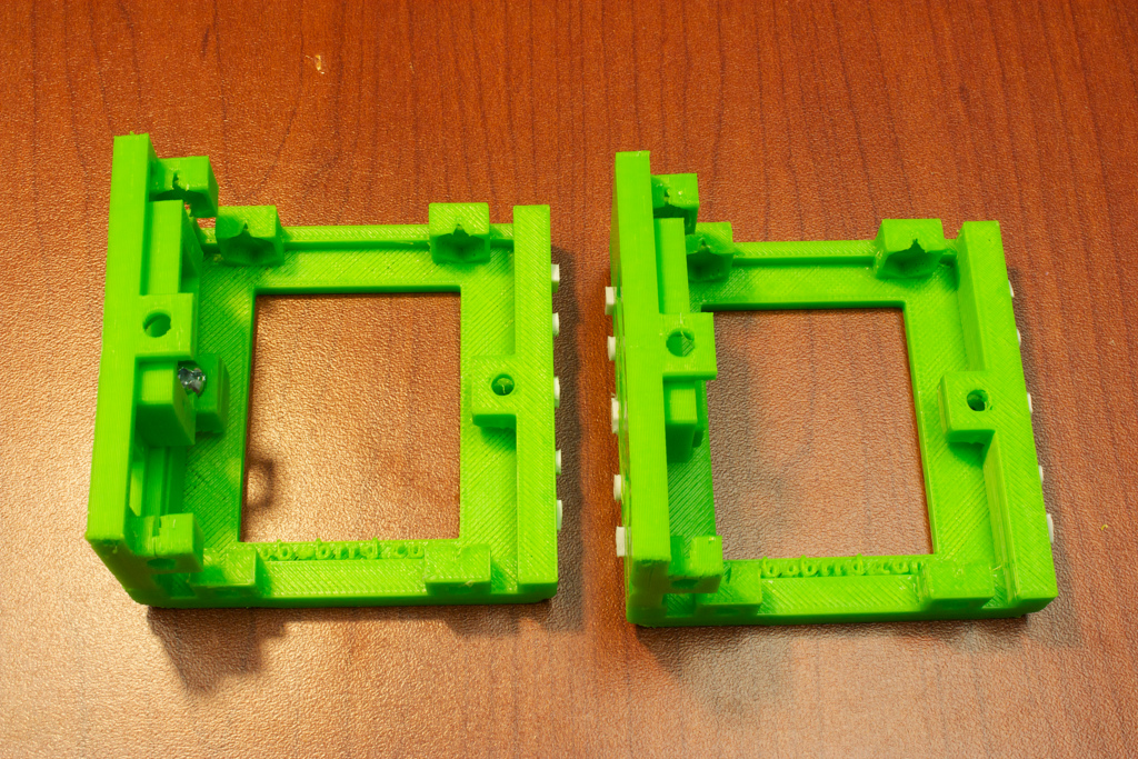
1. Body Front & Side


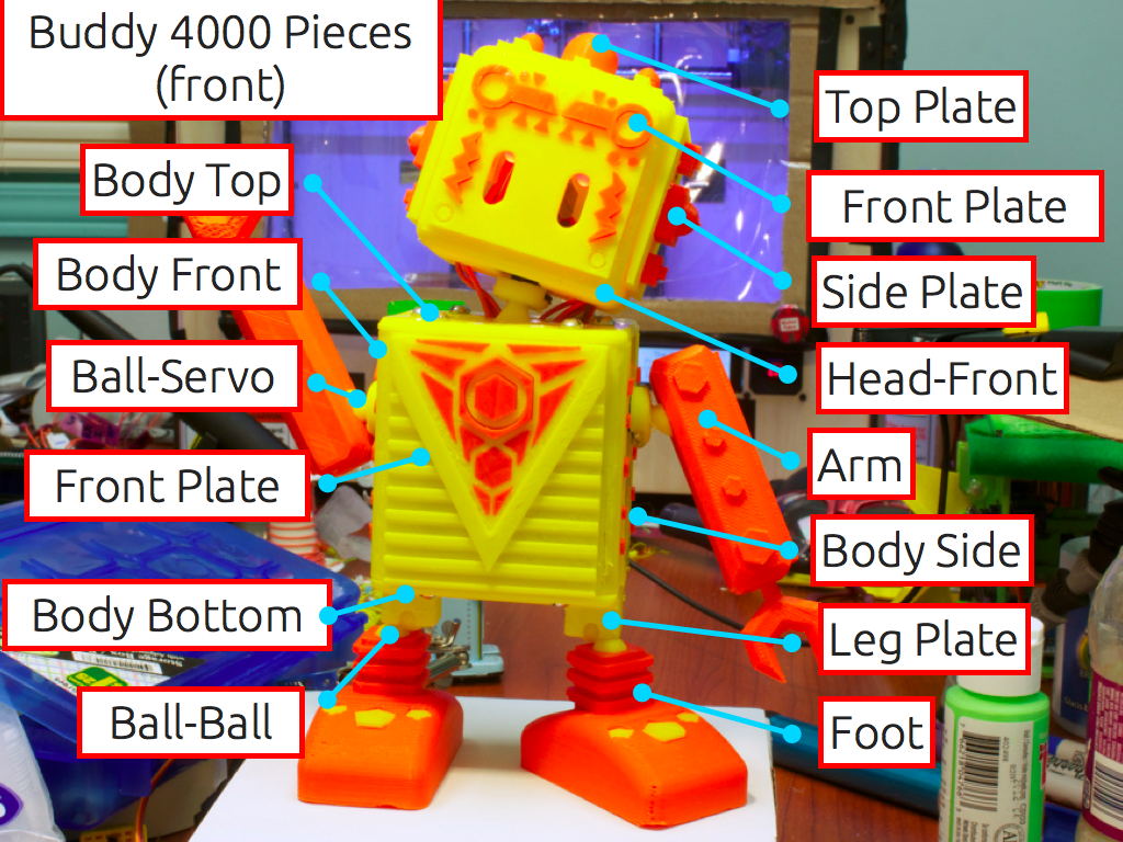
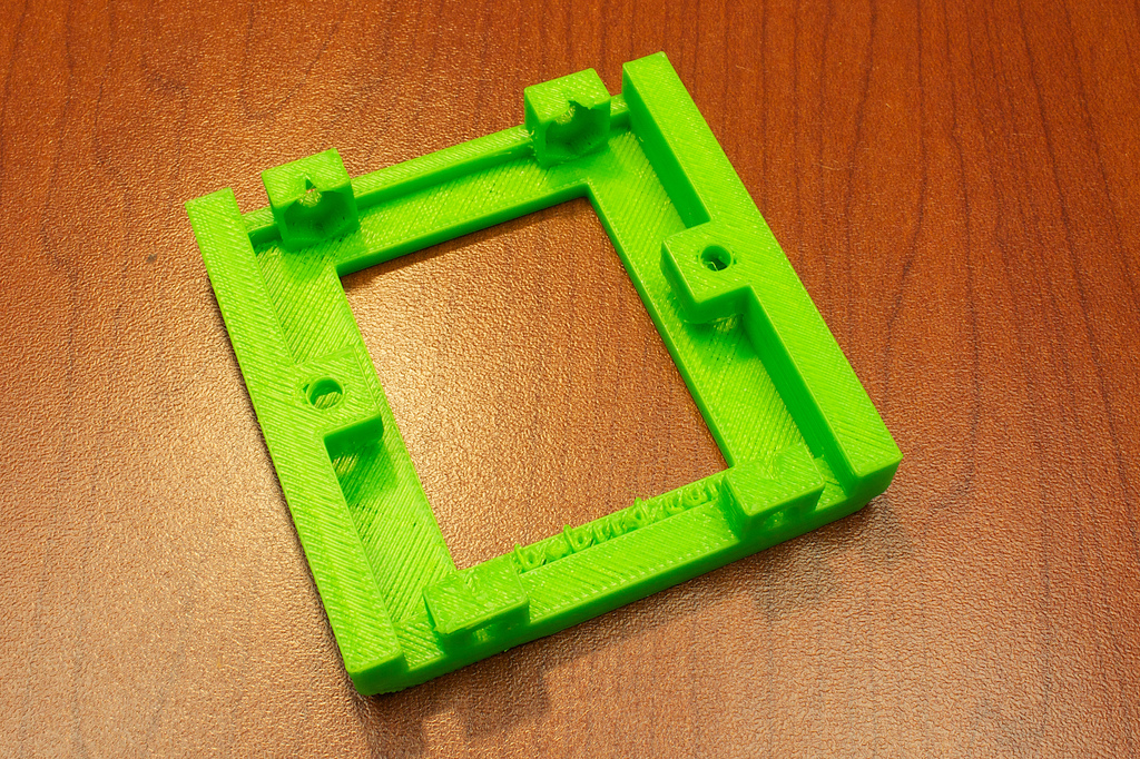
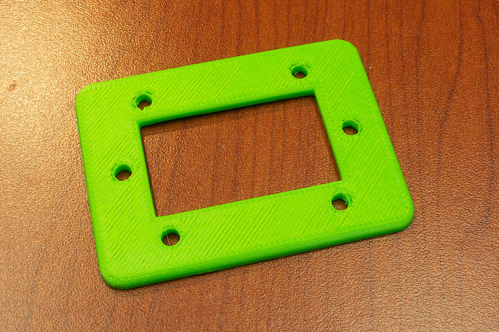
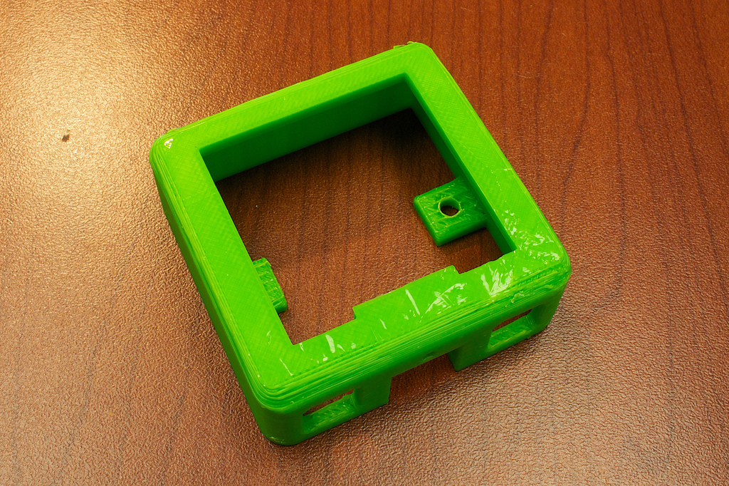
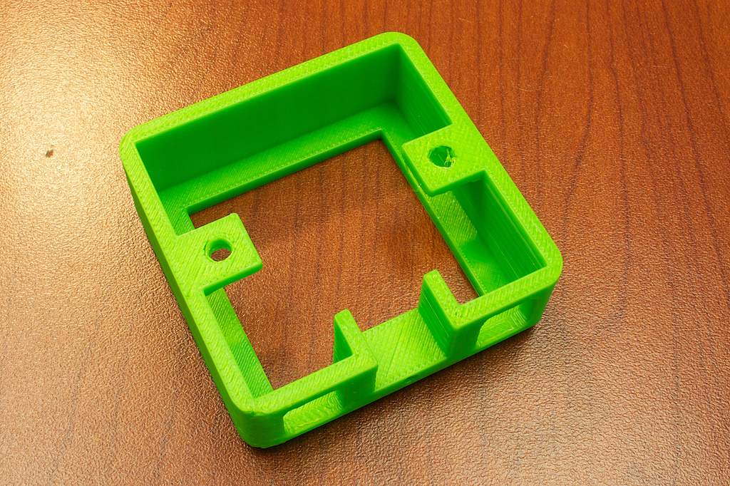
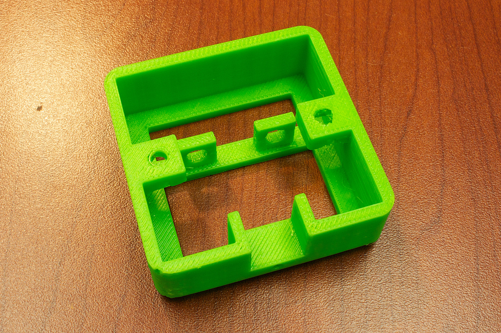
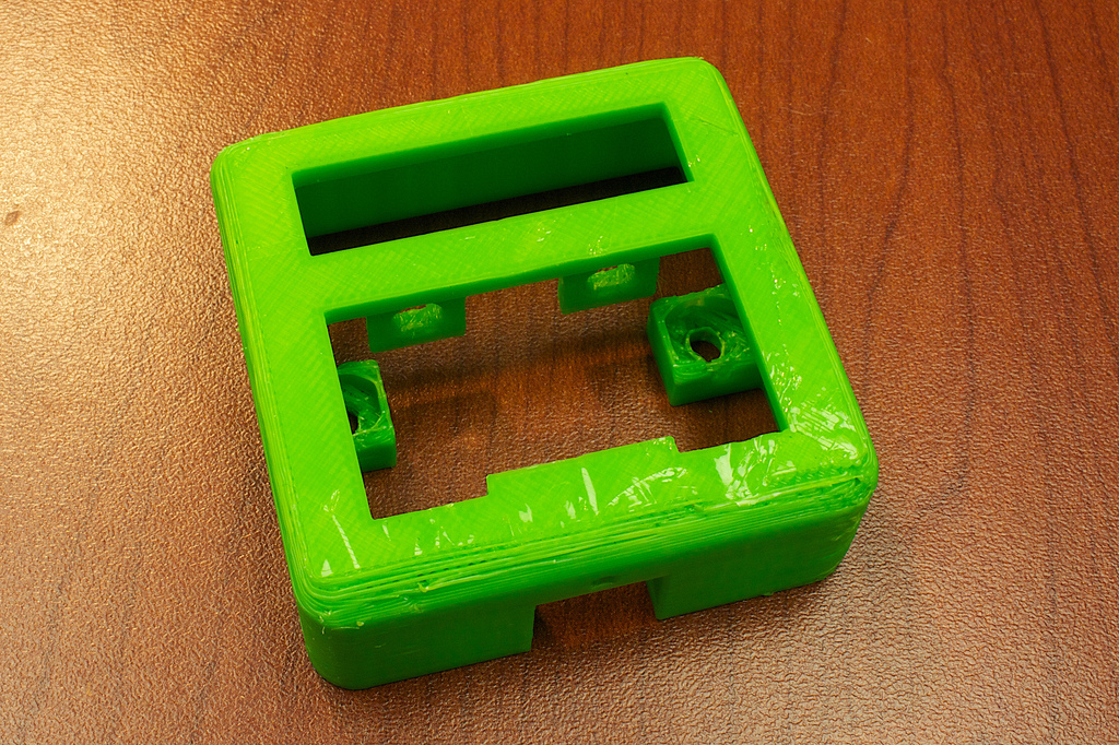
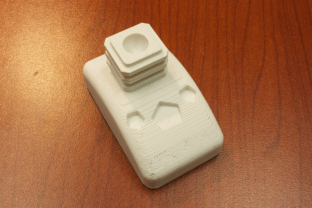
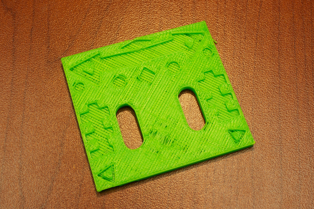
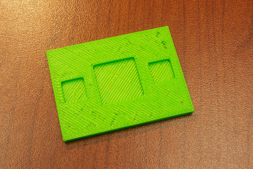
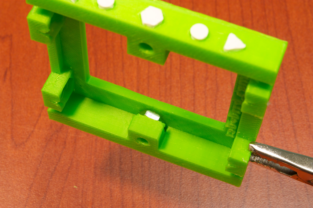
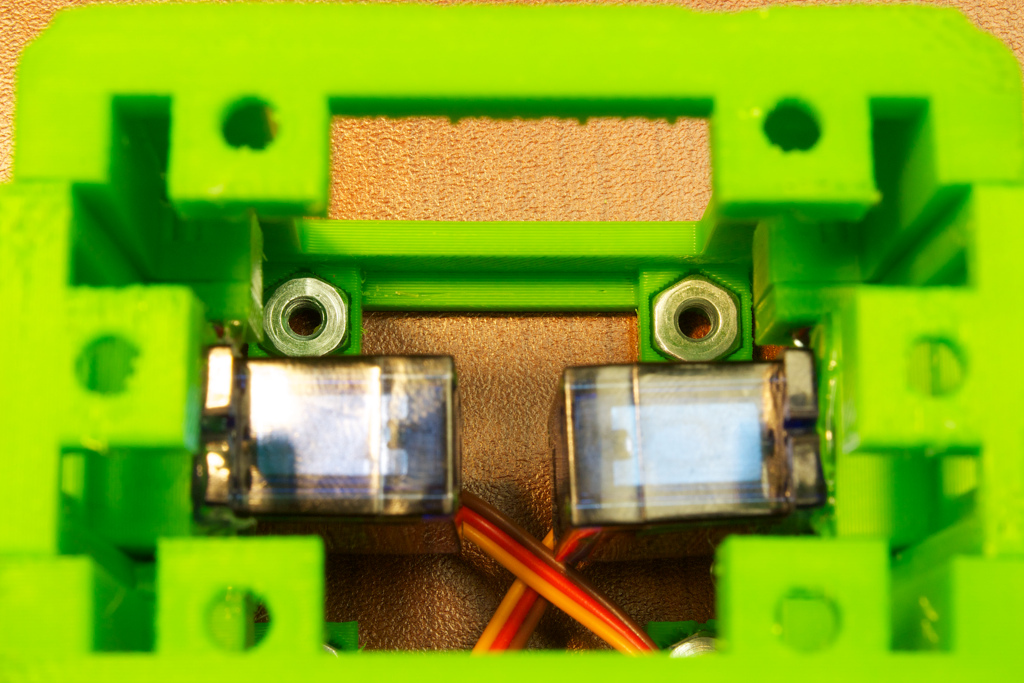
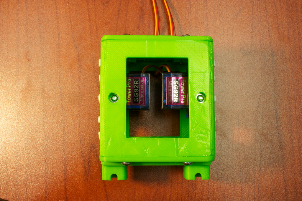
The first step is to begin assembling the main body. First, insert two hex nuts behind the tabs on the Body-Front piece.


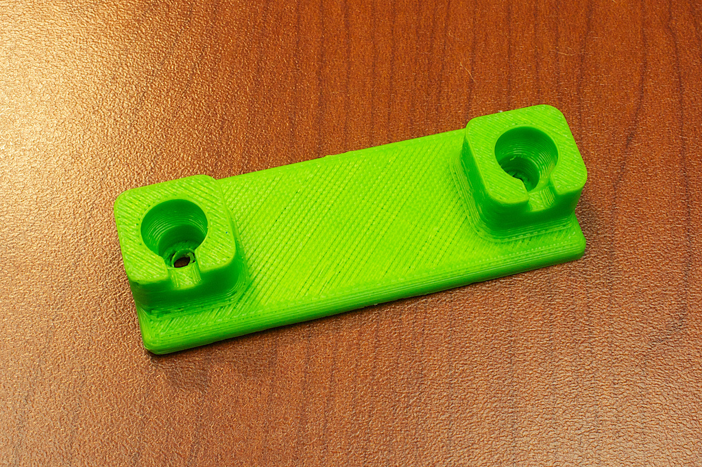
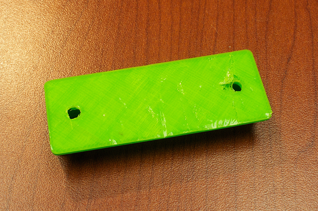
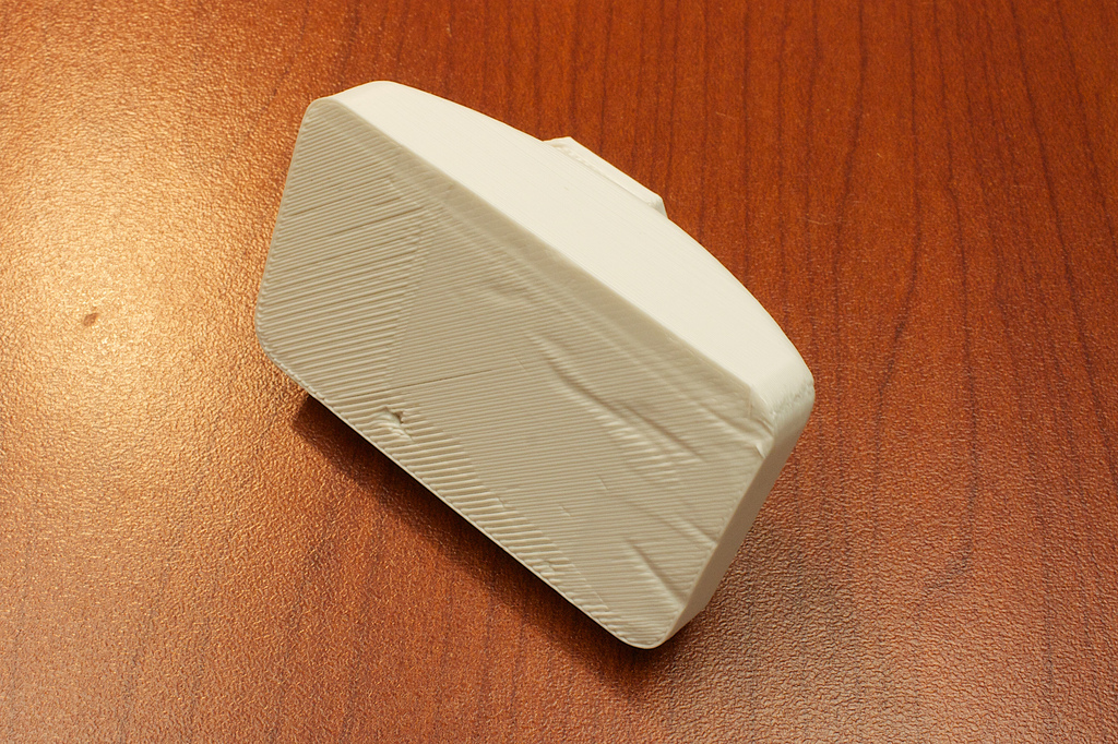
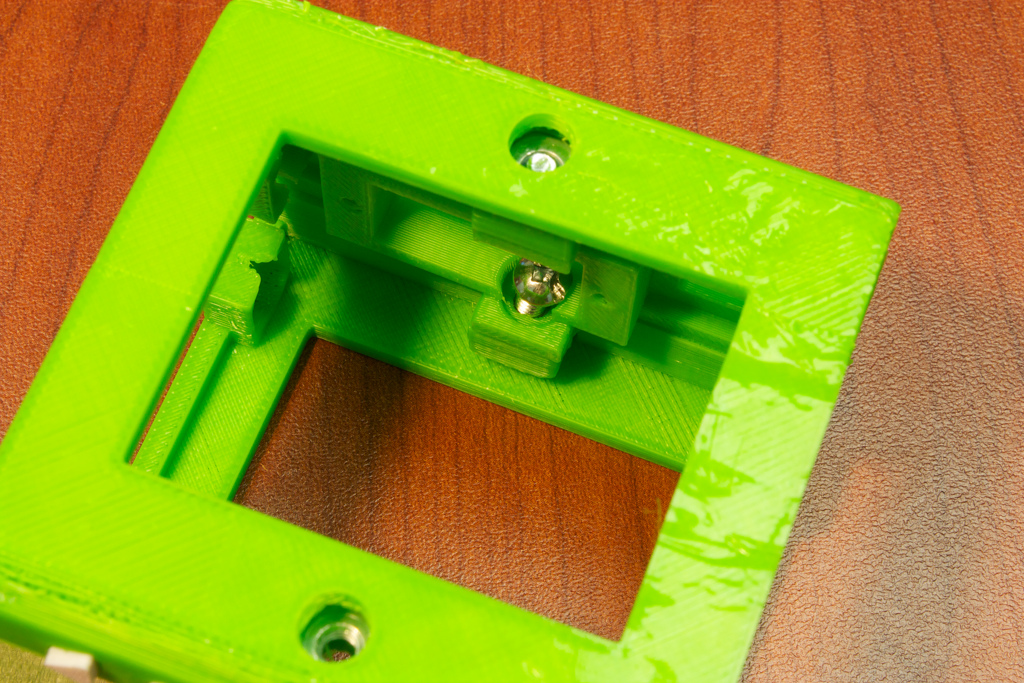
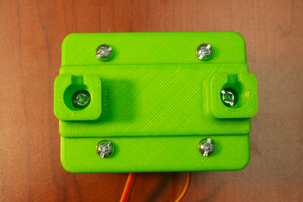
Flip the piece over, and press down through the holes onto the nut so that it fits into the capture area.


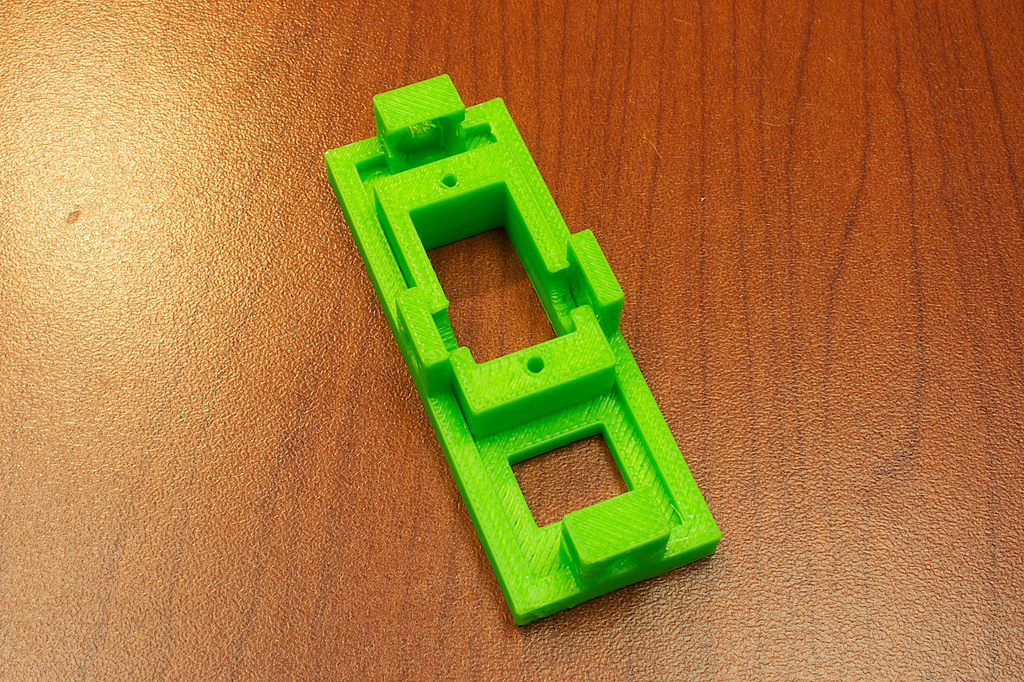
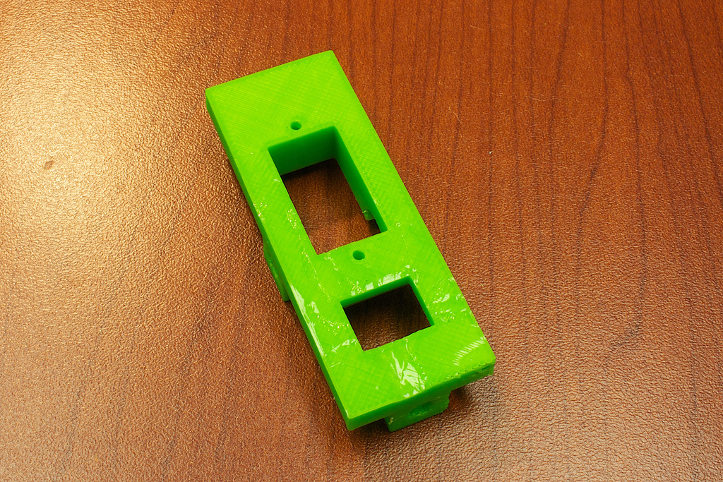
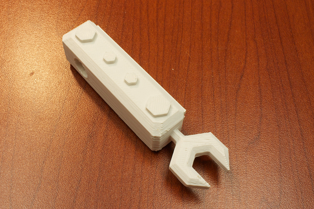
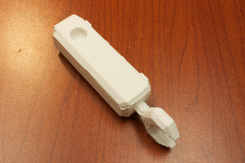
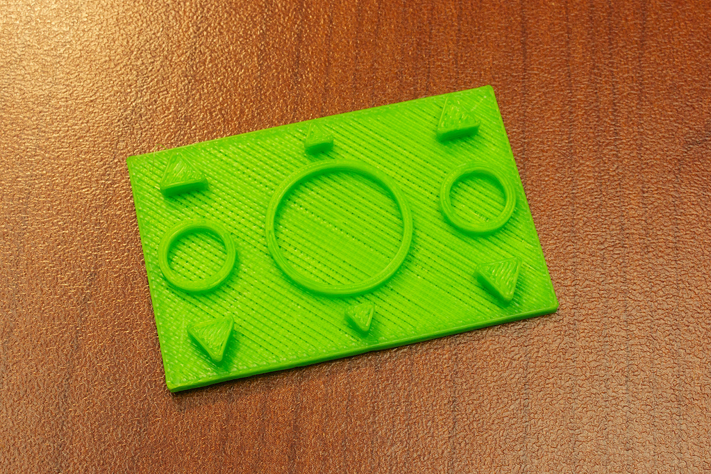
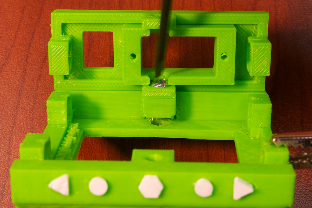
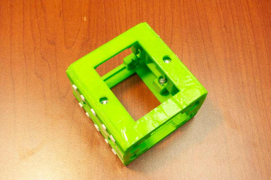
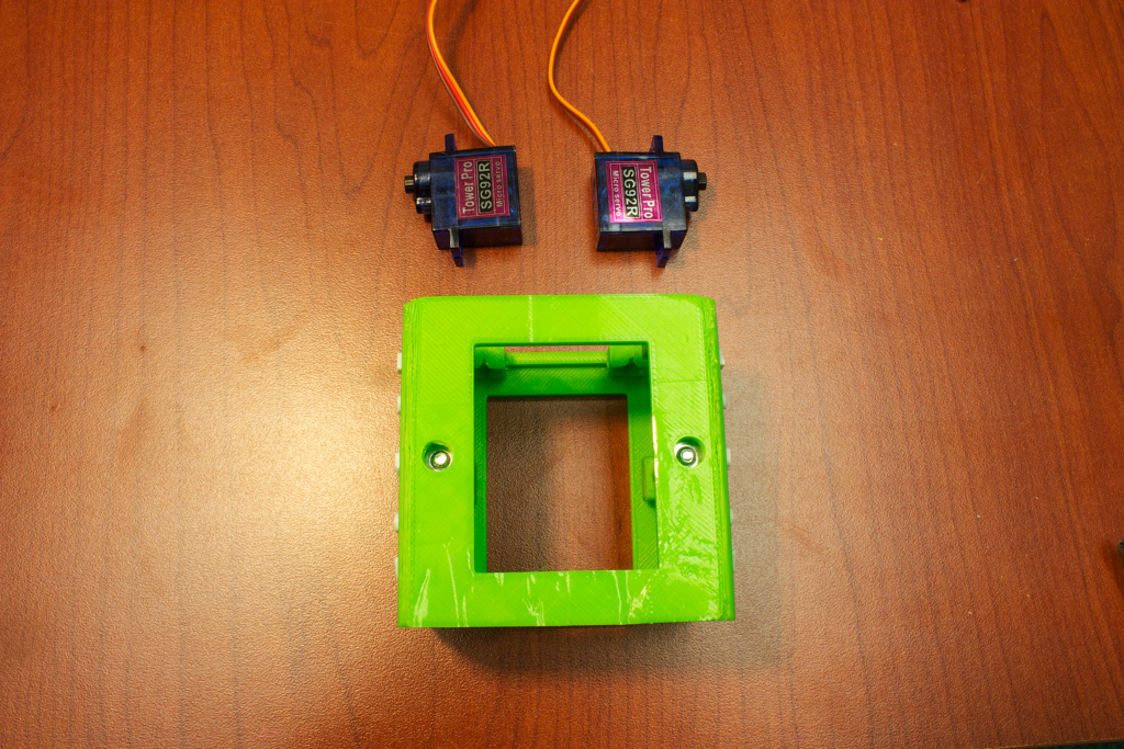
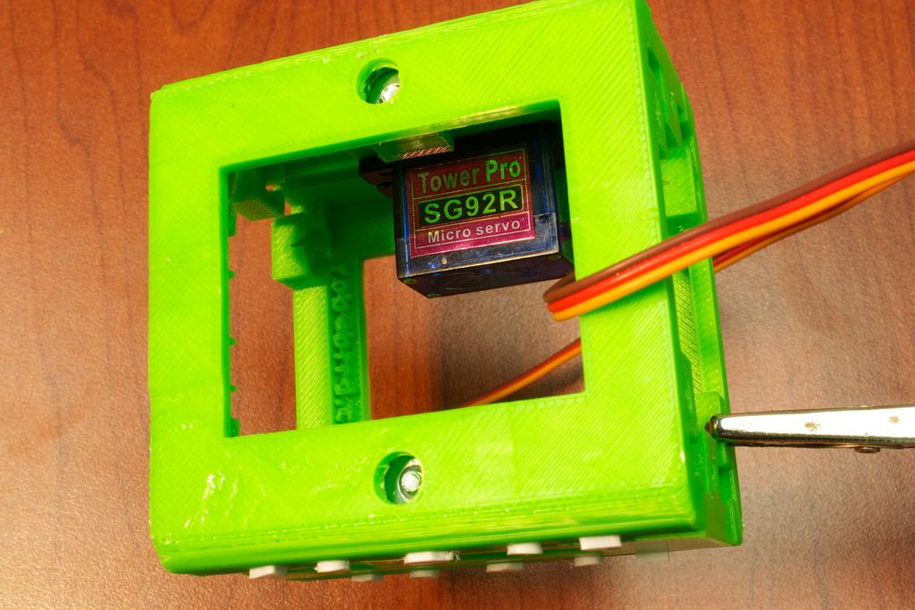
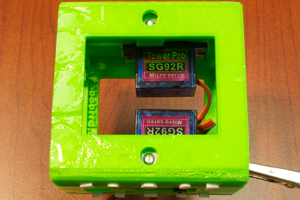
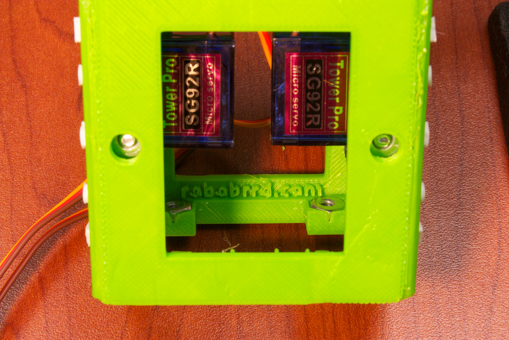
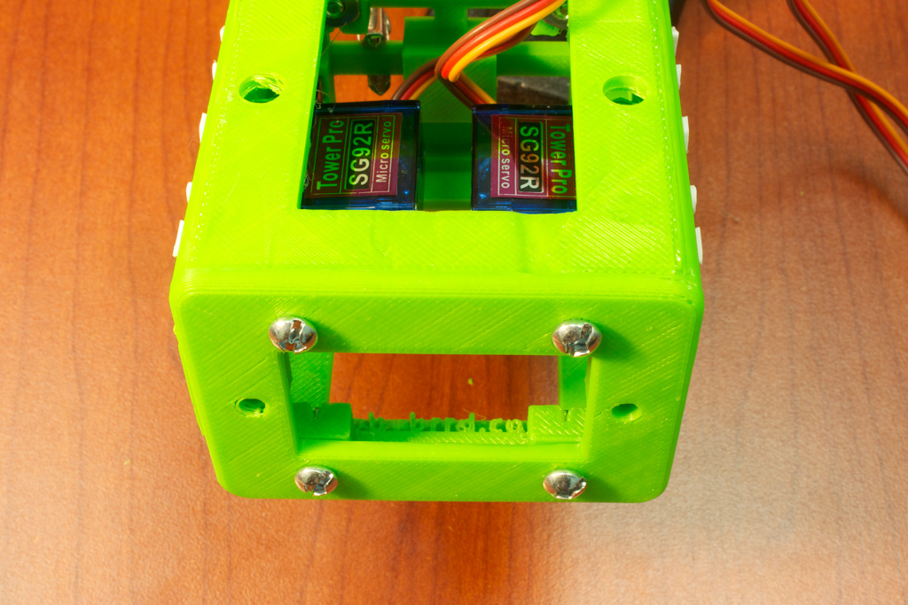
Take a Body-Side piece, and orient it so that the top of the servo holder (the extruded rectangle on the back), is farthest away from the 'robobrrd.com' text on Body-Front. Place a #6-32 3/8" screw through the hole and through the nut. Screw it in until it is slightly tight. See the photo for an illustration of this.


Repeat the above steps for the other Body-Front and Body-Side pieces.


Next up will be attaching these two pieces together.

2. Body Assembly


Place the two resulting pieces together, and add a screw through the Body-Side area through the nut.


Flip the assembly over, and do the same for the other side.


Next up we will be adding in the servos.

3. Arm Servos


For this part, you will need your servos (TowerPro SG92R or similar). We will be adding them into the Body-Side pieces.


Push the servo into its mounting bracket extrusion on the Body-Side piece. The servo horn should be closest to the top of the body, or farthest away from the 'robobrrd.com' text on the Body-Front pieces.


When you have the servos mounted properly, add some hot glue to the tabs to keep them sticking to the piece.


Next up we will be adding the Body-Top piece.

4. Top


Flip over the body assembly so the top is closest to the table. Gather 6 hex nuts and place them inside the captures.


Photo from different angle:


Grab the Body-Top piece and gather 6x 6-32 3/8" screws. Place the Body-Top piece upside down, near the top of the body assembly. Place the screws through the holes and screw them in. The final result should look like this (when viewed from the top):


Next up is the other end: Body-Bottom & Leg Plate.

5. Bottom & Leg Plate


Gather 6 hex nuts and place them in the captures on the other end of the body assembly.


Grab the Body-Bottom piece and 4x 6-32 3/8" screws. Add the screws to the holes on the longer sides of Body-Bottom and screw them in.


Grab the Leg Plate piece and 2x 6-32 1/2" screws. Add the screws to the two remaining holes and screw them in.


This is what the final result will look like


Next up is the assembly for the head.

Build Part 2


There are some more parts to build, let's go on to part 2!

Build Part 2