Soldering
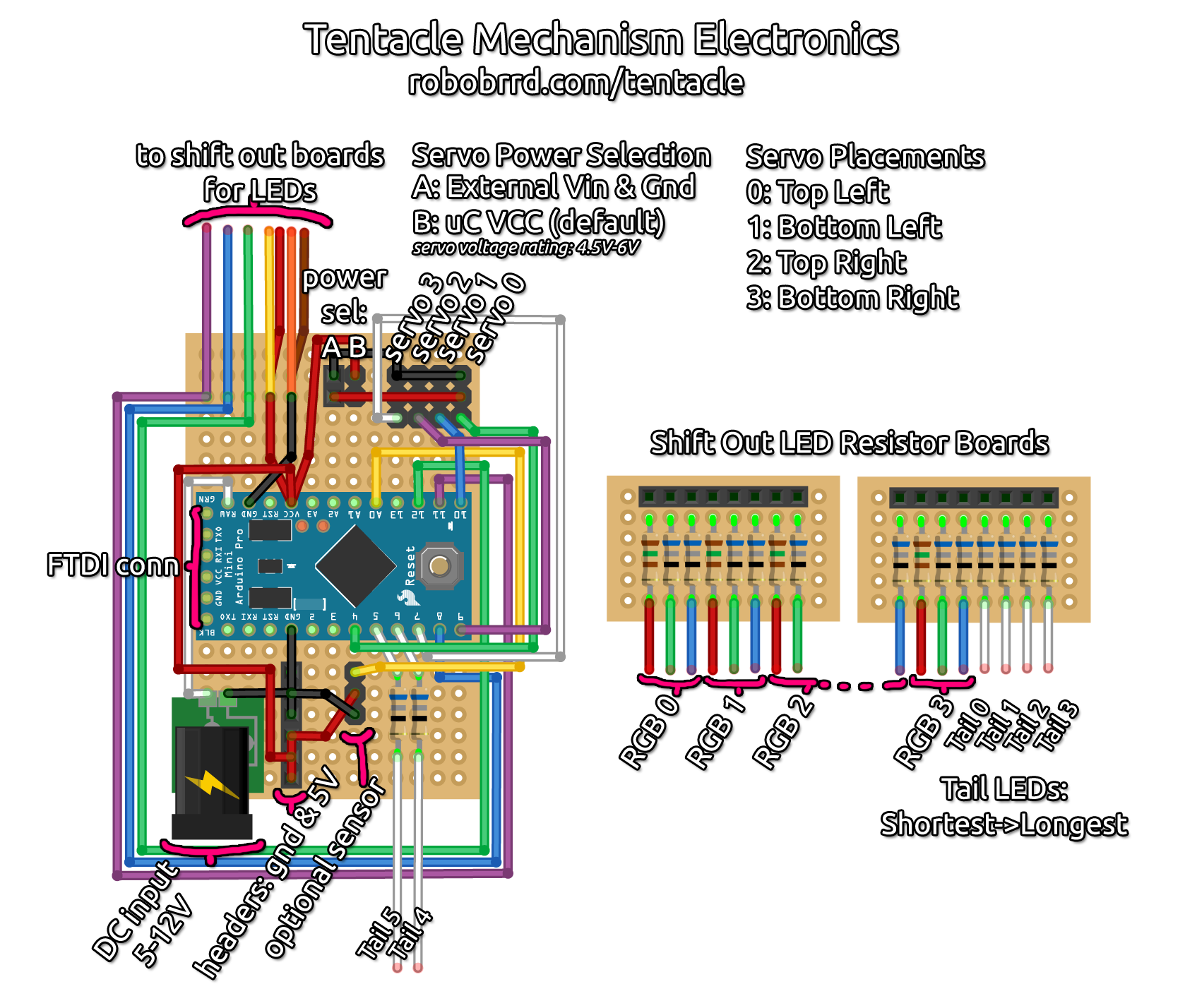
There are many components and wires to solder up for the tentacle mechanism! We will be refering to the board like a cartesian plane, with the origin in the top left corner.
Note: Although we will say "solder to X pin on the Arduino Pro Mini", we mean the corresponding pin from the Arduino through the headers and on the perf board — not actually soldering to the Arduino itself.
Let's begin!
Headers
We will start off with the main headers of the show- the ones for the Arduino Pro Mini! Take 2x 12-female headers and solder the first one starting at (2, 8) spanning to (13, 8). Solder the next one starting at (2, 14) to (13, 14).
Take a 2-female header and solder it at (7, 2) to (7, 3). Take a 2-male header and solder it adjacent, to the right, of that header. So from (8, 2) to (8, 3).
Take 4x 3-male headers and solder them starting at (10, 2) to (10, 4). For the next 3 headers, solder them adjacent to the right of that header. The final header will be starting at (13, 2) to (13, 4).
Take a 6-female header and solder it starting at (5, 16) to (5, 21). Take a 3-male header and solder it starting at (8, 16) to (8, 18).
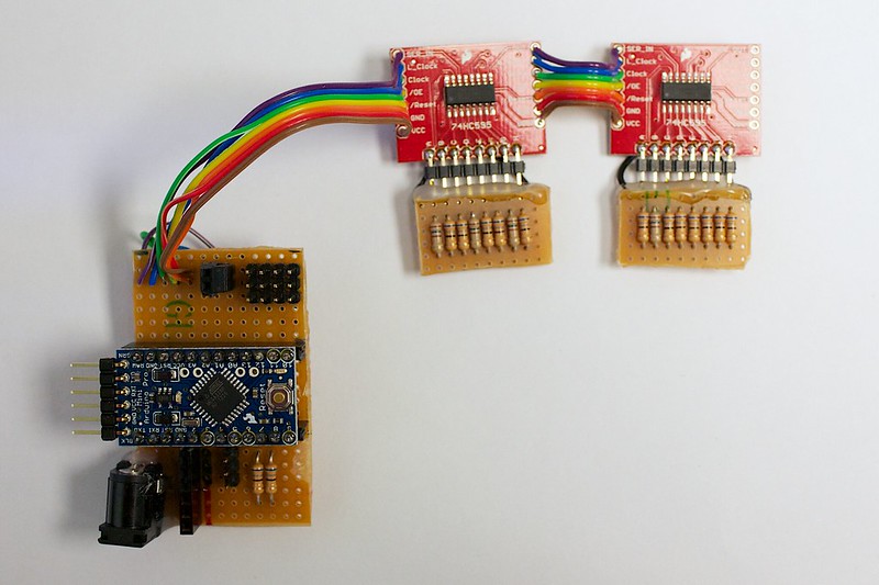
Now for the Shift Out LED Resistor Perfboards, take a 8-female header and solder it at 90 degrees starting at (2, 1) to (9, 1). By 90 degrees, we mean that it will be along the same surface as the board. This way the 595 breakout board will be able to plug in to it along the same way. On the 595 breakout board, solder a 8-male header to its output pins at 90 degrees. Do the same for the other boards as well.
All of the headers are done! Now let's add the resistors.
Resistors
The resistors that you use will depend on the LEDs that you choose. In this case, we only need two values: 150Ω and 68Ω. We will need 4x 150Ω, and 14x 68Ω.
Grab the Shift Out LED Resistor Perfboards and solder in the resistors starting from (2, 2) to (2, 5). Follow the wiring diagram above for the order of the resistors.
The remaining two 68Ω resistors are soldered to the main board. Starting from (10, 16) to (10, 20). The next resistor is soldered adjacent to the right.
That's all for the resistors!
LEDs
All of the LEDs (except two of them), will be soldered to the Shift Out LED Resistor Perfboards. It's a good idea to check which lead of the LED is positive, and/or what colour it is. The first to be soldered are the RGB LEDs, following the pattern of R, G, B (straight forward). You can folllow the wiring diagram above for this.
Solder the wire from each RGB LED to the hole below the corresponding resistor. The Gnd's of the LEDs can go to the empty holes on the sides of the board. We will be wiring a connection from Gnd to the sides. Solder a bridge from the resistor solder pad to the LED solder pad, so that it can be connected together.
The tentacle tail LEDs are wired in from the shortest to longest. Solder the positive wire from each LED to the hole below the corresponding resistor. Same as before, the Gnd's of the LEDs can go to the empty holes on the sides of the board.
To solder the Gnd connection, solder two wires from the shift register breakout to both side rows. Bridge each connection, so all of the Gnd's of the LEDs are connected together.
Moving on forwards!
DC Jack
The DC jack is located in the bottom left corner of the board. Be sure to determine what tabs are positive or negative. It can change from jack to jack, so it's important to always check.
Depending on your jack, you might have to fiddle with the tabs to get them to fit through the holes. Or you can attach wires to the tabs, then hot glue the entire jack to the board.
Wire the positive connection of the jack to the RAW pin on the Arduino Pro Mini. The raw pin can accept 5-12V. Wire the negative connections of the jack to any of the GND pins on the Arduino Pro Mini.
Wiring
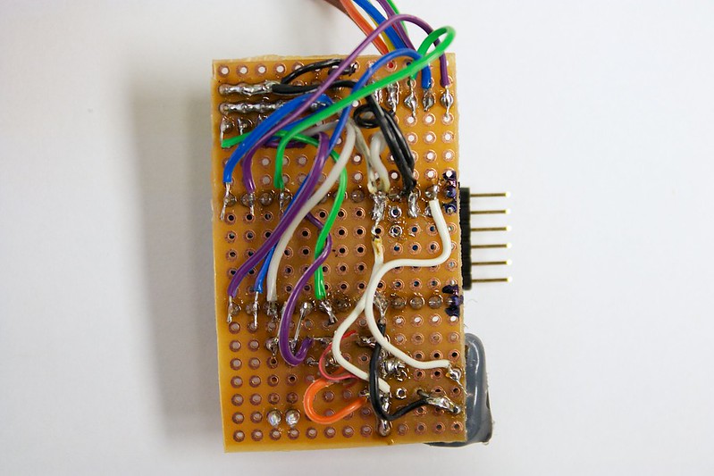
For the wiring, you will be cutting, stripping, and soldering small pieces of wire from pad to pad. The wiring is a tricky task. You might want to take a break before tackling it. You also might want to take breaks while wiring everything (seriously, it's that tedious).
All of the connections can be found on the wiring diagram above. Here is a checklist that you can follow to see if you have wired everything.
- Servos: Gnd, Power, Signals
- Power Sel: Gnd, Vcc, to servo power
- To shift out boards
- Optional sensor: Gnd, Power, Signal
- Gnd & 5V header
- Tail 5 & 4
- LED Gnds
- LED Resistors to headers
- FTDI Header
DONE!
The soldering is done. Take a breath. A breath of fresh air, not tinged by the scent of solder.
As always, it's a good idea to double check all of your connections. Especially make sure to check that you haven't accidentally soldered +V and Gnd together before powering it up! ;)

 Store
Store Robots
 Learn
Learn Community